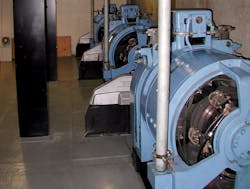
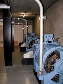
DC motors may not be the wave of the future, but they certainly have a secure place in today’s workplace (see DC Isn’t Dead). Therefore, it’s worthwhile for electrical professionals to take a look at their inner workings and, when the time comes, be prepared to service DC motors.
The very first motors operated on DC because they preceded the development of AC generation and distribution systems. These early models were extremely limited because existing batteries were not capable of providing much power. For this reason, DC motors were little more than scientific curiosities until the late 1800s — when Thomas Edison developed a DC generation and distribution system in Lower Manhattan. As this system spread throughout populated areas, the DC motor found use in mining, manufacturing, and transportation applications. But soon, Nikola Tesla and George Westinghouse came on the scene with their AC generation and distribution system together with viable AC motors, which became dominant except in instances where it was necessary to control the speed and/or direction of rotation of the motor. For elevators, ski lifts, and many industrial uses, smooth speed control and reversibility are essential. Until the relatively recent development of the variable-frequency drive (VFD), AC motors were not used in the above applications.
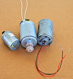
DC motors may have wound rotors with permanent magnets or wound stators. The great advantage of a permanent magnet stator in a DC motor is that the motor is lighter and more compact. Recent developments in permanent magnet technology have resulted in this variation finding its way into more powerful motors (Photo). Maintenance is a key component to a motor’s operation and performance. Let’s take a look at what this entails for DC motors.
Making DC motor repairs
While smaller DC motors are simply replaced when they fail to function as expected, larger DC motors are ordinarily rebuilt as needed. Repairs can range from simple brush and bearing replacement to a total overhaul, including extensive rewinding.
At times, you will come across a DC motor (or generator) with one or more stator magnets that have come loose from the housing. These magnets are very brittle and must be handled carefully. They can be epoxied back in place with high-temperature epoxy. It is necessary to place the magnets precisely in the original position, or the motor’s timing will be disrupted.
If the motor has a wound rotor and stator, the windings may be in bad condition, in which case the motor will have to go to a motor shop for rebuilding. Moisture, vibration, overheating, corrosive atmosphere, or spikes in the power supply can damage windings.
The high-maintenance components of DC motors are brushes and the commutator (see What Makes DC Motors Work?). This is the reason the AC motor, especially the induction variety, replaced the DC motor where speed control and reversibility were not issues.
Brushes were originally made up of stiff copper strands, connected to electrical leads and bundled together, resembling small paint brushes. They would ride along the turning commutator with just the right pressure to maintain electrical contact with a minimum of wear. Too much heat, however, could weld them to the commutator, causing sparking to become a problem.
Today, manufacturers use short carbon bars with concave ends that conform to the cylindrical shape of the commutator. They retain the name “brushes,” despite the fact that the physical makeup and electrical characteristics are different. There is still the problem of sparking — and with increased wear, that issue gets worse. At first, the brushes throw a slight amount of sparks as they ride over the segmented commutator, but after some time, the sparking becomes more intense, eventually resembling a bright gas flame.
If you catch it in time, the brush can be saved. Using a Scotchpad, polish the area of the commutator where the brush rides. With the motor disconnected from the power source, slide a piece of fine sandpaper between the commutator and the brush with the abrasive side toward the brush, working it back and forth to restore the smooth curve of the brush. Clean off any abrasive particles that could make nonconductive hot spots.
If the brush has become too short — or if it appears chipped or crumbly — replace it. Sometimes, when the spring has lost its tension, you can restore it by stretching it by hand.
To summarize, a brushed DC motor requires more maintenance than the common AC induction motor, but excellent speed control and reversibility are achieved by simply adjusting the power supply. Rather than waiting for the DC motor to fail, it is more economical to institute a comprehensive preventive maintenance program so that damaging trends can be spotted early. This is especially true if there are many large motors in the facility.
A stitch in time
A maintenance log should be posted near each motor that is dated and initialed with any pertinent comments. Lubrication, belt tensioning, and the like should be noted as well. A stethoscope is useful for checking bearings, and a thermal imaging device or temperature probe with digital readout will detect heat rise in bearings, windings, or wire terminations before serious damage occurs. Beware of unusual noises. They indicate trouble within the motor or changes in the load, binding, or alignment problems that could spell trouble down the road.
An excellent diagnostic tool is the clamp-on ammeter. Capable of handling much higher current levels than a multimeter, this device will take non-intrusive measurements of the current flowing in each individual conductor. If there is a gradual rise in current over a period of time, it means that either the internal motor insulation is beginning to deteriorate, or the load level on the motor is increasing.
If an oscilloscope is available, use it to check the power supply ahead of the rectifier to see if there are excessive potentially harmful harmonics that would cause heating of the neutral. At the rectifier output, look for a reasonably clean DC signal with no increased ripple that would indicate capacitor degradation.
NEC mandates
A part of any comprehensive preventive maintenance program is verification of the original installation to ensure it complies with the NEC. Article 430 [Motors, Motor Circuits, and Controllers] covers the installation of these devices from the point of view of eliminating hazards that arise from the use of electricity. A major focus is the correct size of the branch circuit, overcurrent protection, and disconnecting means.
For motors, calculations are done in a manner that differs sharply from other electrical equipment. Most electrical loads draw more current when they are first switched on than after they are fully powered up. This is true to an even greater extent for motors than for other loads — so much so that different methods for overcurrent protection are needed. If these special methods are not employed, then the circuit will trip out before the motor starts. To allow the motor to start, a 2-tier approach to overcurrent protection is used.
The conventional branch circuit short circuit ground fault protection, as located in the service-entrance panel or in a load center at the downstream end of a feeder, is permitted to be greater than for non-motor loads. The values are given in Table 430.52 [Maximum Rating or Setting of Motor Branch-Circuit Short-Circuit and Ground-Fault Protective Devices]. These values are displayed as percentages of full-load current based on the type of motor and the type of overcurrent device. For DC motors, the percentage is 150, unless there is an instantaneous-trip breaker, in which case the percentage is 250.
The second tier of overcurrent protection is motor overload protection, which is within or in the controller adjacent to the motor. It protects the branch circuit wiring and motor in case the motor is overloaded or fails to start.
These two levels of overcurrent protection allow the motor to start without tripping the overcurrent device. At the same time, they ensure safety for the entire installation. One of the ways the procedure for sizing out the installation is unique for motors is that rather than using the full-load current as it appears on the nameplate, you take the horsepower from the nameplate and refer to one of the tables that appear near the end of Art. 430. For DC motors, this is Table 430.247 [Full-Load Current in Amperes, Direct-Current Motors]. The figures in this table are used to determine circuit size, overcurrent device rating, and ultimately the size of the branch circuit conductors from the ampacity tables in Chapter Three, Wiring Methods and Materials.
Herres is a licensed master electrician in Clarksville, N.H. He can be reached at: [email protected].
SIDEBAR 1: DC Isn’t Dead
A good many DC motors remain in service today that offer excellent performance characteristics in terms of smooth speed control and reversibility. At the small end of the continuum, DC motors are everywhere. Ink jet printers, besides stepper motors, usually contain two DC motors. Children’s toys, computer cooling fans, cordless tools, electric automobiles, and trolling motors for boats are a few more examples.
Even though there is the downside of brush and commutator maintenance, replacement is a rather big job when you consider that new mounts and electrical controls would be needed. When it comes time to replace or rebuild, the decision is often made to “stay DC.” The DC option — while somewhat low tech in comparison to an AC motor with VFD — still works well in existing environments, especially where the rectifier and controls are in place and viable.
SIDEBAR 2: What Makes DC Motors Work?
All DC motors originally had brushes and a commutator. In the traditional DC motor, brushes perform two functions. First, they are necessary to get the electrical power into the rotor. If the rotor were wired to the outside power supply, the wires would quickly twist and break off as it began to turn. The second purpose of the brushes is that, in conjunction with the commutator, they switch the direction of current flow so the magnets in the rotor reverse polarity as needed to keep the motor turning. It works quite well because whatever speed the motor goes, the commutation occurs at the correct rate.
What makes this work is the fact that the commutator is segmented. It is easy to visualize a 2-pole motor where the commutator consists of two segments and switching events occur twice in the cycle, 180° apart. While this arrangement is satisfactory for demonstration projects, actual working motors have more poles. For a 2-pole motor, there is no torque when rotor and stator poles are 90° apart. If the motor happens to stop at or near this position, it will have to be restarted manually. Secondly, in this position, the two brushes bridge the commutator segments so that there is a short circuit. The result is brush and commutator heating and rapid wear, wasted power, and damage to the power supply. Of course, the answer is to provide more poles. Small brushed DC motors have three poles, which greatly improves their performance.
About the Author
David Herres
Licensed Master Electrician
David Herres is a licensed master electrician in Stewartstown, N.H. He can be reached at [email protected].


