When machine vibration increases, one of the first questions to ask is: “Is a failing bearing causing the vibration?” In the case of rolling element bearings, it’s not difficult to separate vibration caused by a failing bearing from other common problems, such as unbalance, misalignment, or looseness. But sorting out whether vibration stems from a failing rolling element bearing (i.e., bearing vibration) or process sources (such as flow-induced and background vibration) can be more demanding.
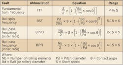
The secret to determining if a rolling element bearing is the source of the vibration is to identify the frequency at which a flaw on a roller or raceway will impact the mating bearing component. Luckily, there are four bearing fault frequencies for rolling bearings that can be calculated as a function of shaft speed (rpm), based on bearing geometry (see Table).
Even without calculating the actual bearing fault frequencies, vibration from many non-bearing sources can be identified or eliminated. Unbalance, misalignment, looseness, vane pass, and gear vibration all occur at multiples of shaft rotating speed, whereas bearing vibration does not. The technical term for this is synchronous versus non-synchronous vibration. Bearing vibration is non-synchronous.
Identifying bearing vibration
While the first step in identifying bearing vibration is simply to determine if the vibration is non-synchronous, definitive diagnosis usually requires more rigorous analysis.
In its early stages, bearing vibration will exhibit very low amplitude. Therefore, it will be difficult to separate from background vibration and flow-related vibration on fans, blowers, and pumps. Detection requires accurate calculation of actual bearing fault frequencies.
Note that the equations in the Table are based on the actual rotating speed of the shaft when the vibration data was recorded. It is not acceptable to use nameplate or other nominal rpm for these calculations, nor is data from process control systems sufficient. The rpm must be measured at the machine with an accurate tachometer or from the vibration signal.
“Locate rpm” function
If an accurate tachometer is not available, shaft speed can be determined by finding the 1 × rpm peak from residual unbalance on the vibration spectrum with the “locate rpm” function available on many vibration analyzers. Spectrum analyzers lacking this function may not correctly indicate peak readings for common electric motor speeds if used at resolutions of less than 1,600 lines. The “locate rpm” function should also be used to identify the peak frequencies of suspected bearing vibration. Again, higher resolution spectra yield greater accuracy.
Occurrence of sidebands
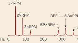
Another identifying characteristic of bearing vibration is the presence of sidebands — a series of equally spaced peaks on either side of the bearing fault frequency that are caused by amplitude modulation of that frequency. For example, the vibration amplitude will increase as a flaw on the inner race rotates into the bearing’s load zone (at the bottom for most bearings) and decrease as it leaves the load zone. The spacing of the sidebands (1 × rpm in this case) is referred to as the delta frequency (see Figure). Similar modulation can occur with other bearing fault frequencies at various delta frequencies. For instance, when a flaw is on the rolling element, a fundamental train frequency (FTF) delta frequency is possible.
Even if rpm has been determined accurately, calculated bearing fault frequencies can be suspect if the bearing geometry is not entered into the calculation accurately. The pitch diameter, ball diameter, and contact angle for the same size bearing can vary by manufacturer (and even by bearing type or production date for a given manufacturer), so bearings must be identified correctly to ensure accurate fault frequency calculations. In addition, most vibration analysis software references a database of manufacturer-specific bearing dimensions and vibration frequencies. Therefore, this feature of the software is only useful for analyzing bearings that have been accurately identified by type and manufacturer.
The presence of families of non-synchronous vibration in the 2 × rpm to 20 × rpm range, including sidebands, is a strong first indication of bearing vibration that can be confirmed with accurate data on shaft rpm and bearing geometry. Inaccurate data, on the other hand, will lead to erroneous conclusions.
Vogel is a pump and vibration specialist at the Electrical Apparatus Service Association (EASA), St. Louis. He can be reached at [email protected].


