Diagnosing & Understanding Motor Bearing Currents
In the age of energy efficiency, engineers are often excited about the potential cost savings associated with variable-frequency drives (VFDs) and their ability to operate motors to match demand loads. While VFDs can significantly alleviate electricity costs, they can also dramatically reduce a motor’s lifespan. Shaft voltages generated from the common-mode output of VFDs lead to arcing across a motor bearing. Over a short period of time, this can lead to audible noise, not to mention subsequent motor failure.
With the growth of VFDs in the market today, as well as documented shaft voltage failures, industry standards have begun to take notice. Despite the increased understanding of a correlation between motor shaft voltages and VFDs, there is still a lack of awareness that across-the-line motors can experience similar problems. Regardless of the type of motor starter being used, engineers should be aware of the symptoms of shaft voltage and bearing currents. Diagnosing the problem is crucial, given the fact that for most facilities an outage can be costly or even life threatening in certain industries, such as health care or nuclear applications.
Introduction to the phenomenon
In order to understand why shaft voltages occur in induction motors, you must be familiar with the theory behind their development. Induction motors operate by a rotating magnetic field, which creates a force that rotates the motor. To establish this magnetic field, the motor must be started by switching to a power source in the facility. The most common means of switching to a power source and starting a motor is a procedure known as “across-the-line,” in which the motor is started at full voltage directly from a breaker. In an across-the-line started motor, the power source of the motor is 3-phase power, in which all phases have the same magnitude, phase angles are offset by 120°, and the sum of the phases is zero. Ideally, since the sum of the phases is zero, minimal current will flow from the motor frame to ground.
VFDs have gradually begun to replace across-the-line starters due to their reduction of motor inrush currents and their ability to adjust motor speed. Contrary to across-the-line starters, VFDs establish an initial magnetic field by rectifying the AC to DC voltage and subsequently inverting the voltage back to AC via high-speed switching. Because the voltage output of the VFD is a result of high-speed switching, the waveform more closely resembles a square wave instead of a sine wave. As a consequence, an imbalance is present between the three phases that are entering the motor leads, referred to as common-mode voltage, examples of which are shown in Fig. 1 and Fig. 2.
As soon as the motor is started with a VFD, the common-mode voltage imbalance searches for a path to ground, and a parasitic coupling of the rotor and stator windings develops. Once the oil film in the dielectric breaks down, voltage levels increase on the motor shaft, and the lowest impedance path for the current imbalance becomes the motor bearings themselves. Voltage begins to arc across the bearing at high frequencies (Fig. 3), leading to electrical discharge machining (EDM).
EDM discharges continue to arc across the bearings, oftentimes leading to audible noises emanating from the motor itself. Discharges occur continually during motor operation and begin to melt the surface of the bearings. Over time, pitting of the motor bearings occurs at the point of discharge. If not appropriately diagnosed, the motor bearings will become damaged — and eventually be completely destroyed. In some situations, a new motor can be destroyed within a few months.
Risk factors
The development of some level of bearing current is inevitable; however, there are several key risk factors that can exacerbate the effect. Although the following risk factors are perhaps the most well known, numerous others can also play an important role.
Motor frame size — Motor bearing currents have a direct relationship to motor size. Specifically, motors above 450 hp have been found to be the greatest candidates for bearing currents, due to the higher likelihood of magnetic asymmetry in the construction of the motor windings. While large motors will experience some amount of bearing currents, motors powered from VFDs introduce additional magnetic asymmetry from common-mode voltage.
Rough handling — Motors are at an increased risk of shaft voltage if they were handled roughly during shipment. Oftentimes, damage can occur in the factory, in transit, or when the motor is being lifted onto its pedestal. Minor motor damage during shipment may not cause noticeable problems with motor performance; however, it increases the likelihood of magnetic asymmetry leading to bearing current development.
Improper/inadequate grounding — Proper grounding of standard across-the-line starter motors, although oftentimes not properly designed, is more understood in the industry and in the standards. Improper grounding interferes with the normal flow of current through the motor frame and the grounding conductors, and fails to provide a low-impedance path. Under these conditions, current searches for a lower impedance path to ground, which could often be through the motor bearings. Once the dielectric breaks down in oil film protecting the bearings, the flow of ground current through the bearing leads to arcing and damage. For motors on VFDs, the common-mode voltage makes proper grounding even more crucial. Because the common-mode voltage ensures that there will always be more substantial ground current, it may be difficult to prevent bearing damage, unless industry standards and manufacturers’ recommendations are followed. To help alleviate the imbalance present in the VFD output, shielded cable could be used to aide in draining current to ground. Such information is often present in manufacturer literature, but not always applied in the field.
High carrier frequencies — Research has shown that VFDs operated at higher carrier frequencies lead to a higher rate of current discharge pulses and EDM damage. For plant operators, operating motors at higher carrier frequencies is beneficial due to the reduction in motor ambient noise; however, the risk of motor damage increases. To alleviate these concerns, personnel must try to find the balance between lower carrier frequencies and the audible sound of a motor. In many cases, this quantity can be set in a drive by fine-tuning the carrier frequency in small increments to find the best acceptable level. Although an equal trade-off is not always feasible, the sizable cost of motors may favor operating at lower frequencies.
Lack of awareness — A key risk factor is the lack of proper documentation and awareness. Although the development of motor bearing currents is documented in industry standards, many engineers and technicians are often not aware of the potential problems, especially when it comes to using VFDs.
The inherent difficulty of diagnosing a bearing current problem further increases the likelihood of a damaged motor. As arcing develops through the motor bearings, the first telltale sign of an issue is an increase in the noise generated by the motor. Because most motors are located in areas away from personnel, it is often difficult to ascertain whether or not the noise has increased. Once arcing develops, microscopic pitting of the bearings, referred to as “frosting,” becomes apparent. Frosting is sometimes visible to the naked eye; however, it is also more often microscopic. This compounds the difficulty of making a proper diagnosis, because damage cannot be viewed unless the motor is disassembled. If allowed to continue, arcing continues to damage the bearing and creates large grooves in the bearings, commonly referred to as fluting. At this point, the motor bearing will need to be replaced.
Industry standards
Industry standards have been gradually revised over time to keep pace with the increase of VFD usage. The key motor standards (NEMA MG1: Motors and Generators and lEEE 112: Standard Test Procedure for Polyphase Induction Motors and Generators) now include references on acceptable bearing current levels.
The first reference in NEMA MG1 can be found in Article 14.32, which pertains to AC motors powered from VFDs or variable voltages. This reference goes on to state “experience shows that although this is generally not a problem on this class of machine, shaft voltages higher than 0.5mV (peak), when tested per IEEE 112, may necessitate grounding the shaft and/or insulating a bearing.” Another mention can be found in Article 31.4.4.3 on large definite purpose inverter-fed motors. This article delves into greater detail, describing the phenomenon, as well as recommending bearing insulation in cases where bearing voltage is greater than 300mV. Additionally, this statement details the increased probability of bearing currents in motors larger than 500 hp, due to the higher likelihood of magnetic asymmetry during construction.
While NEMA MG1 makes it clear about bearing currents in VFDs, as well as potential solutions, it does not apply the same clauses to standard across-the-line motors. Although VFDs are far more likely to generate motor bearing currents, standard motors also experience the phenomenon if exposed to the risk factors discussed previously. As a result, many engineers and technicians often would not consider testing for shaft voltages, unless they were unfortunate enough to have encountered the problem previously.
For testing motors in the field, you should rely on the procedures highlighted in IEEE 112. This standard reiterates the theory of bearing currents as well as possible solutions. Similar to NEMA MG1, the sections in this standard only apply to VFDs.
Test procedures
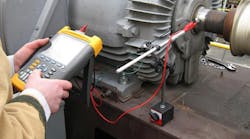
Detecting bearing currents is perhaps one of the more difficult tests to perform, because the shaft of the motor must be exposed and the motor must be energized during the test. To overcome this obstacle, several vendors have developed a carbon brush assembly that can be connected to an oscilloscope. This allows technicians to maintain a safe distance away from the motor during the test. Other methods of testing are available, such as using a high-impedance voltmeter instead of an oscilloscope. However, a lack of accuracy and waveform plots makes this type of test less useful.
The first step in performing a shaft voltage test, once the fiberglass rod and oscilloscope are assembled, is to power down the motor and expose the shaft. With the oscilloscope grounded to the frame, the carbon brush is applied to another grounded location on the motor. This enables the technician to obtain the level of ambient noise present, which should then be subtracted from the measured readings taken on the motor.
After the ambient noise measurement has been completed, the carbon brush is placed directly to the spinning motor shaft. Several measurements should be recorded, with efforts to ensure the entire waveform can be viewed on the oscilloscope (Photo). Careful observation of the waveform should reveal if a sharp spike in voltage is present, which would be indicative of a shaft voltage discharge. Voltage in excess of 0.5mV (peak-to-peak) is oftentimes cause for further investigation. However, in VFDs, the nominal value will almost always be in excess of 0.5mV. The examples discussed below indicate various examples of shaft voltage tests.
The oscilloscope screenshot shown in Fig. 4 presents clear evidence of shaft voltage, with a peak-to-peak value of 74.3V. This is well above the IEEE 112 allowable value of 0.5mV, as well as the manufacturer’s allowable voltage of 1V to 2V for VFDs. A peak voltage of 74.3V imposed upon the shaft likely means that the bearing will not survive much longer unless remedied.
The shaft voltage of 11.6V in Fig. 5 shows another clear example of bearing currents. In this example, the motor is a standard across-the-line unit, which is not connected to a VFD. This motor was initially tested because it was emanating loud audible noises. The contractor on-site had experienced shaft voltages on a previous project and was quick to remember to do a motor shaft test. After discussing the situation with facility personnel, the contractor discovered the motor had been handled roughly during its shipment. Damage to the motor windings likely occurred during shipment, creating a magnetic imbalance.
When testing a motor, it is often useful to test the “B” motor to compare values. The screenshot shown in Fig. 6 is the “B” motor of the across-the-line motor that was dropped during shipment. Clearly, there is no evidence of shaft voltage or damage to the bearing in this waveform. Oftentimes, comparing two similar motors can help pinpoint if the problem lies in the motor itself, with transient voltage power supplies, or in a faulty grounding system.
Once a motor bearing concern has been identified, it can be difficult to remedy the situation. In the case above for the across-the-line motor, the problem was resolved by shipping a new motor, which did not show any evidence of bearing currents and subsequent damage during shipment. In VFD applications, bearing currents are unavoidable, and engineers must make efforts to simply lower the value as best they can.
Once improper grounding and transient voltage supplies are ruled out, engineers often have few solutions to lower shaft voltages. Many engineering firms specify insulated motor bearings, which create a high-impedance ground path and avoid damage to the bearing. However, there is no guarantee that ground current will not find another harmful path to ground, such as through a pump coupling. Furthermore, insulated bearings are often cost-intensive. Ceramic bearings and grounding brushes are options to explore; however, these are also costly solutions.
Grounding rings have become established in the industry as a possible remedy to shaft voltages. Carbon brushes are physically inserted onto the shaft, with connections being made directly to the motor frame. In theory, a lower impedance ground path is created, which minimizes paths through the bearing itself.
Summing it up
As VFDs gain increased market share, further research will help identify the best solution to combat motor bearing currents. Although the industry is aware of the potential negative consequences of VFD drives on motor bearings, there is not enough industry awareness that damaged across-the-line motors can exhibit the same concerns.
In many situations, due to the lack of awareness in the standards, many engineers are not aware of the potential problem unless they experienced the issue first-hand on a project. Given the cost implication of a failed motor, it is certainly a lesson worth remembering.
Gonski is an electrical project manager at the Keystone Engineering Group, Inc., in Frazer, Pa. He can be reached at, [email protected].


