When placing air terminals on a flat roof or gently sloping roof per NFPA 780-14, many recognize the 50-ft maximum spacing between air terminals rule (Sec. 4.7.5), but overlook the section’s second sentence. Give it a second read to avoid a non-compliance situation.
Have you ever considered that the required air terminal would need to be 50 in. tall? Why is this, you ask? Before we get started, let’s review some basic geometry equations. They should help you visualize this three-dimensional sphere.
The Cartesian equation of a sphere: (x – x0)2 + (y - y0)2 +(z - z0)2 = R2, where x0, y0, z0 is the center of the sphere, and R is the radius of the sphere. Any point on the surface of the sphere can be defined by its coordinates (x, y, z).
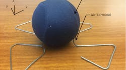
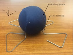
The concept of the rolling sphere is that as you roll an imaginary sphere with a radius of 150 ft, it must not touch a protected surface (Photo 1). Instead, the path of the sphere should touch a series of air terminals connected to cables meant to redirect the path of lightning safely to ground through a low resistivity path. In the example case of the 50-ft maximum spacing per NFPA 780, we can make a few observations. To satisfy the 150-ft rolling sphere, the lowest point on the z-axis of sphere must not break the plane of the roof level, assuming there are no “protected elements” above the roof.
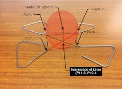
When defining the four air terminals Cartesian coordinates, you have:
• Bottom of air terminal at Point 1: (0,0,0)
• Bottom of air terminal at Point 2: (50,0,0)
• Bottom of air terminal at Point 3: (50,50,0)
• Bottom of air terminal at Point 4: (0,50,0)
The bottom quadrant of the sphere “resting” on four equi-distance air terminals of the same height would occur at the coordinates of the intersection of the midpoint of lines between Point 1-Point 3 and Point 2-Point 4 (Photo 2). The bottom quadrant point occurs at (25,25,0).
Given that the sphere radius (R) is 150, the center lies directly above the quadrant at (25, 25, 150).
Substituting the center, x-axis and y-axis values for any given point from the bottom of each air terminal location, we can solve for their required height “z” using the Cartesian equation of a sphere, which is 4.2 ft or 4 ft - 25/7 in.
Let’s look at an example. Solving for z-value at Point 2 is simply:
(50-25)2 + (0-25)2 + (z-150)2 = 1502
z = 4.23
So, if we need 4-ft, 25/7-in. air terminals for 50 ft maximum spacing, what is the maximum spacing for a standard 2-ft air terminal? Think of the same 150-ft sphere, but with a horizontal circle or belt around the sphere at 2 ft off the roof instead of
4 ft, 25/7 in. Again, the Cartesian equation of a sphere can be used, this time concurrently solving for x and y distances.
We will use an array of air terminals in a square pattern for simplicity, where x and y distances are the same. We must acknowledge that the maximum distance resides on the hypotenuse of the square; x and y distances are derived using the hypotenuse multiplied by the cosine of the angle, being 45°.
With R = 150 and z = 2, solve for the difference of x and y values for Points 1-3 and Points 2-4.
Since we are evaluating a square, we can substitute the difference in x values for the difference in y values, resulting in 2(x-x0)2 + (2-150)2 = 1502. So, the distance between Point 1-3 is 48.83 ft or 48 ft, 10 in. Evaluating the spacing between Point 1-2 would be 48.83 cos (45), which is 34.53 ft or 34 ft, 61/3 in. So, when using 2-ft air terminals, maximum spacing on a flat roof with nothing standing above the roof, the maximum spacing is 34 ft, 6 in. to satisfy the 150-ft rolling sphere criteria.
Do not let the graphic in NFPA 780 and the maximum spacing language lull you into a sense of false comfort. Take my advice, and freshen up your geometry skills. While you’re at it, take a few minutes to thank your geometry teacher who will help keep your designs compliant. A sincere thank you to mine — Central High School’s Ms. Cora Huddle.
Markley, P.E., LEED AP BD+C, RCDD is the chief electrical engineer at Mason & Hanger, a Day & Zimmermann Co., Glen Allen, Va. When not arranging paperclips and stress balls on his desk, he is responsible for technical oversight of the firm’s electrical engineering staff. He can be reached at [email protected].


