Many loads are mainly resistive; thus, they’re rated in watts (i.e., true power). Simply stated, these loads have a very small reactive component, which means an apparent power rating (VA) would not be appropriate. One example is a hair dryer. Although these handheld units have a motor that’s considered an inductive component, the current draw on the motor is very small compared to the heat strips in the device. Another example is a unit heater in a shop area. Again, these units have an inductive motor, but the current draw of the heater coils is much greater. Additional examples of resistive loads include incandescent lamps, water heaters, and cooking ranges. Larger resistive loads are labeled as kilowatt (kW) loads instead of watt (W) loads.
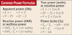
You might recall from your earlier studies that apparent power (VA) is both the true power (resistive) and the reactive power (inductor and capacitor) components of a circuit. (For common power formulas and definitions, see Brush Up). One of the most common loads is a motor. In addition to its horsepower (hp) rating, its nameplate will list voltage (V) and current (A). Have you ever ran the calculation using the hp rating of a motor (e.g., hp = 746W)? If so, you would find the running current does not equal the current calculated using the power equation: I = P ÷ E. For example, a 1-hp single-phase motor at 240V has a nameplate current listing of 8.8A, but 746W ÷ 240V equals 3.11A. Why aren’t they equal? Because the hp listing of the motor isn’t meant to be used in a current calculation as it doesn’t include the inductive reactance component (among other factors).The hp rating is just a listing of the motor’s ability to do work.
Transformers are rated in kVA because apparent power represents the total current (and voltage) the transformer can supply. The total full load amps (FLAs) that a 25kVA transformer can deliver to a single-phase load at 240V is 104A. Again, this is calculated by the power equation: I = P ÷ E. It’s up to the electrician to ensure the connected load to the transformer (e.g., apparent or true) doesn’t exceed the transformer’s full current rating.
Gen-sets are mechanical devices comprised of an engine turning the shaft of a generator, which generates power to supply a load. The generator is always rated in kW with a power factor of 80%. All generators are considered to be rated at 80% power factor unless the nameplate states differently. The rating of a generator requires the load to be examined with respect to kW (i.e., true power). This approach allows the electrician to accurately size the generator.
For example, say a generator is to serve a building made up of several different types of loads: lighting panels for resistive lighting (higher power factor), lighting panels for fluorescent lighting (lower power factor), power panels feeding HVAC equipment with motors (poor power factor), receptacle panels feeding general office equipment (lower power factor), and so on. As you can see, the building’s power factor is difficult to calculate at any one time. If a generator was rated at 100kVA and the total building load was 100kW, the building power factor of 80% would create a 125kVA load. This generator would be undersized for the load. By rating the generator at 100kW with an assumed 80% power factor, the chance of incorrectly sizing a gen-set is lower. Unlike a transformer, which is providing power by means of mutual inductance, a generator is directly coupled to an engine. A load larger than the generator’s maximum kW rating will physically load the engine so that it can’t deliver the hp required by the generator.
The kVA rating of a generator can be calculated by dividing the kW by the power factor (kVA = kW ÷ 0.8). But as mentioned above, the tendency to use the calculated kVA of a generator oftentimes results in an undersized generator for the load served.
Ball is the director, inside curriculum & electronic media with the Electrical Training ALLIANCE in Upper Marlboro, Md. He can be reached at [email protected].
SIDEBAR: Brush Up
Apparent power (measured in VA) is simply the multiplication of the circuit’s total current and voltage. It includes both the true power component (i.e., resistive power measured in watts) and reactive power component (i.e., reactance power measured in VARs). In theory, purely inductive circuits contain no true power component because of the absence of the resistive component.
True power (measured in watts) is the actual power used by the load or better explained as the resistive part of the circuit that performs the work. True power can be produced only when current and voltage are both positive or both negative. In theory, we discuss purely resistive circuits but in real situations they do not exist because the circuit conductors themselves produce both some amount of inductance and capacitance.
Reactive power is measured in volts-amps-reactive (VARs). It is the power that flows back into the source from the inductors (and capacitors). It is this opposing power that affects the power factor of the circuit. Even though this opposing reactive power is not desired, without inductors (magnetism) we would not have motors and transformers.
The power factor is a ratio of the true power (watts) to apparent power (VA). It is ideal to design a system that would have a 95% power factor. An increase in reactive power (VARs) causes the power factor to decrease. The decreased power factor means increased wasted power used to perform the work. The electric utility company oftentimes penalizes the customer for poor power factor because of the wasted power.
