A specialized segment of the electrical construction and maintenance industry, AC motor control is an area that requires specific knowledge in order to troubleshoot motors effectively and ensure smooth operations. This means gaining a clear understanding of ladder diagrams and ladder logic, which enable the automation that drives motors. The combination of input devices that either manually or automatically sense a condition — and the corresponding change in condition performed by the output device — make up the core of motor control. Let's take a closer look at what's involved in learning the symbolic language of motor control.
First, it's important to discuss the term “logic” for a moment. In the study of digital electronics, devices are used that operate in either an ON or OFF state. A specialized branch of mathematics called Boolean algebra analyzes this relationship with two numbers: a zero (representing the OFF state) or a one (representing the ON state). These two numbers comprise the binary number system.
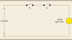
The most common logic functions are the AND, OR, and NOT functions. Think of a single-pole light switch in your home that controls a 100W light bulb. The switch can either be off or on, thereby representing a zero in the off state and a one in the on state. Now imagine placing two single-pole switches in series to control the same 100W light bulb. In this condition, switch No. 1 and switch No. 2 have to both be on to light the 100W bulb. This is an example of an AND operation. Figure 1 represents the AND circuit just mentioned. Logic relates to ladder diagrams because input functions in series constitute an AND operation, while input functions in parallel constitute an OR operation.
You will encounter two types of ladder diagrams: the 2-wire control circuit and the 3-wire control circuit. The 2-wire control circuit is shown in Fig. 2. This circuit is used to start a motor for some industrial process. The components in a 2-wire control circuit are a maintained contact switching device (S1), a relay coil (M1), and the thermal overload relay contact (OL). The sequence of operations is fairly simple. When S1 is closed, the coil of magnetic motor starter M1 is energized and the motor starts, provided the running overload current is within the values of the overload relay OL. To stop the motor, S1 is simply opened.
A 3-wire control circuit is shown in Fig. 3. Again, this circuit is used to start a motor for some industrial process. The components in a 3-wire control circuit are a momentary pushbutton (STOP), a momentary pushbutton (START), a normally open relay contact (M1), a relay coil (M1), and the thermal overload relay contact (OL). The sequence of operations here is a little more complex. When the start button is pressed, the coil of magnetic motor starter M1 is energized and the motor starts, provided the running overload current is within the values of the overload relay OL. However, there is one very important difference: A normally open contact of magnetic motor starter M1 seals around the start button to latch the circuit. To stop the motor, the STOP button is pressed, which, in turn, breaks the latch and de-energizes the coil of magnetic motor starter M1, stopping the motor.
What components make up a full-blown ladder diagram? There are several types of input and output devices. For the purpose of this article, we will focus on conventional electromechanical devices. See Fig. 4 for a list of common symbols used in ladder diagrams and motor control circuits.
Input devices can first be classified as momentary contact and maintained contact devices. Momentary contact devices are spring-loaded and are classified as normally open and normally closed devices. The designation “normally” refers to the state of the device in its resting position — when no external stimulus is acting upon it. The contact arrangement of switching devices can also be classified as SPST, SPDT, DPST, DPDT, 3PDT, etc. The first two letters refer to the number of “poles,” and the last two letters refer to the number of “throws.” For example, SPST refers to a single-pole, single-throw contact while 3PDT refers to a 3-pole, double-throw contact. A fractional manual motor starter useful for single-phase motors (1 hp and lower) can either be an SPST for 120V applications or DPST for 240V applications. A green start button is an example of a normally open momentary pushbutton, while a red stop button is an example of a normally closed momentary pushbutton.
Maintained contact devices are not spring-loaded. Instead, they remain in either an ON or OFF state. They can also be classified as normally open and normally closed. An emergency stop is an example of a maintained contact device.
Temperature-sensing devices commonly used in motor control applications are thermostats and thermocouples. A thermostat relies on the thermal expansion/contraction of a bimetal, while a thermocouple relies on a principle known as the Seebeck effect. Two dissimilar metal wires are joined together in a loop with one end being the hot junction; the other being the cold junction. A difference of potential is generated in the loop in response to temperature change. Each of these devices sense temperature change and then presents a contact closure for use in a control circuit.
Motion-sensing devices commonly used are photoelectric controls and proximity controls. Early versions of photoelectric controls had an incandescent lamp transmitter and a cadmium sulfide photocell receiver. Modern versions of the photoelectric control have pulsed infrared transmitters and solid-state photo-detector receivers. They work on the principle of beam interruption to sense motion and then present a contact closure to the control circuit.
Proximity controls sense motion when an object passes by the sensing target on the device. They can detect metallic as well as non-metallic objects. They operate on the principles of magnetism and capacitance, and then present a contact closure to the control circuit.
Limit switches are the most versatile devices in terms of motion detection. Available in a variety of operator mechanisms and contact arrangements, they work on the principle of physical contact between an object and the operator mechanism to present a contact closure to the control circuit.
The most commonly used liquid level sensing device is the float switch, which operates on the principle of buoyancy. The float is suspended in a liquid bath. As levels of the liquid rise and fall, the float moves. This movement presents a contact closure to the control circuit.
The most commonly used pressure-sensing device is the pressure switch. The diaphragm in a pressure switch monitors the change in pressure and presents a contact closure to the control circuit.
Other types of input devices include the foot switch, the selector switch, or even the contact of a control relay or a timing relay. These are all mechanical devices that present a contact closure to the control circuit.
Outputs of the control circuit can be relay coils, pilot indicating lights, or audible devices. To use the generic term “relay coil,” we need further classification into magnetic motor starter, contactor, and relay. A magnetic motor starter is a relay with a coil and contacts as well as running overload protection by means of thermal overload relays. Bi-metallic thermal overload relays are units made of a heater coil that heats a coil of wire to a specified temperature based on overload current, and a bi-metal unit that expands/contracts and operates a contact. Solder pot thermal overload relays use a similar heater coil and a eutectic solder that melts under overload conditions and correspondingly turns a ratchet wheel to operate a contact. The contact arrangement on the thermal overload relay is normally closed. However, it will open under excessive current conditions and de-energize the coil of the magnetic motor starter and consequently disconnect the motor. Contactors are also relays that switch high load currents but do not provide running overload protection via the thermal overload relay. Control relays are usually designed to switch small control circuit currents. Common types of timing relays are ON-delay (delay on operate), OFF-delay (delay on release), interval delay, and repeat cycle delay. Time delay relays are used for timing in a control circuit.
Pilot indicating lights are used to provide visual indication of a function or to verify that a certain operation is either on or off. Audible sounding devices are used to indicate trouble with a process or alert the user to a particular situation.
Now that you've been introduced to the more common input and output devices that make up a ladder diagram, next time we'll explore in more depth how 2- and 3- wire control circuits tie the control circuit with ladder diagrams into motor operation. Look for the next installment of “Motor Facts” in the June 2007 issue.
Vidal is president of Joseph J. Vidal & Sons, Inc., Throop, Pa.


