Low-Voltage Suspended Ceiling Power Distribution Systems
Among the revisions in the 2014 NEC are some new Articles, one of which is Art. 393. As with most Chapter 3 Articles, this one exists to address a particular type of product.
Low-voltage suspended ceiling power distribution systems (CPDSs) solve several problems. In recent years, the once-rare low-voltage devices have become ubiquitous, and the sheer number of low-voltage applications (see What’s It For?) greatly complicated the installation job. Avoiding “rats nest syndrome” became an increasingly tougher challenge.
How is the CPDS a solution? By way of analogy, imagine if you were wiring an office with 120V lights and receptacles, but breaker panels didn’t exist. You just start mounting each breaker to a spot on the wall. After about eight breakers, it’s a mess.
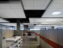
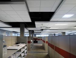
That’s pretty much what low-voltage system installers were working with prior to the advent of the CPDS. With this analogy, you can understand the many problems a CPDS solves in terms of installation, troubleshooting, repair, and maintenance. And, of course, it makes for a much neater installation at a lower cost (Photo 1).
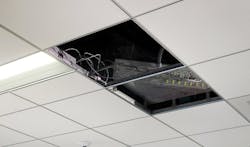
What exactly is a CPDS? In Photo 2, you see a distribution box for an installation that’s under construction. Notice how this box is supported; this aspect is integral to the definition of a CPDS. To qualify as a CPDS, the system must:
• Serve as a support for a finished ceiling surface.
• Consist of a bus bar and bus bar support system.
• Distribute power to utilization equipment supplied by a Class 2 power supply (see What’s a Class 2 Power Supply?).
You can use CPDS in:
• Dry locations indoors, but not in damp or wet locations [393.10, 393.11].
• Residential, commercial, and industrial locations, but not in hazardous locations or concealed locations.
• Spaces used for environmental air, but only if conforming with 300.22(C) and using enclosures listed for use within an air-handling space with adequate fire-resistance and low smoke producing characteristics.
Additionally, you can use CPDS for listed utilization equipment meeting the characteristics described in 393.10(1) but not for lighting in general or critical care patient areas.
In addition to the limitations above, CPDS cannot be installed:
• Where subject to corrosive fumes or vapors (e.g., battery rooms).
• Where subject to physical damage.
• As part of a fire-rated floor-ceiling or roof-ceiling assembly (unless specifically listed as part of that assembly).
Installation
When a Chapter 3 Article addresses a specific product, Part II is typically titled “Installation.” In keeping with this pattern, Art. 393 begins Part II with permitted/not permitted uses (which we just covered).
However, there’s a problem. Being new, Art. 393 has some rough edges. One of those is the fact that subsection 393.14 is also titled “Installation.” This can be a bit confusing. You can start making sense of this by breaking 393.14 down into its components — as if it’s really two subsections:
1) 393.14(A). Supports.
2) 393.14(B). Insulated conductors.
Beware, though. There’s another twist. Subsection 393.30 is titled “Supporting and Securing.” From a workflow viewpoint, the information in 393.14(A) really belongs under 393.30.
Let’s look at insulated conductors first (and then come back to supports). You can use Chapter 3 wiring methods. You can also use Class 2 cable if it’s supplied by a listed Class 2 power supply, and the installation conforms to Parts II and III of Art. 725. Now, about those supports… .
Supports
In a logical workflow, you would mount the CPDS first and then run conductors to it. The CPDS support requirements are in 393.30. So really, the support requirements begin there and then double back to 393.14(A).
The gist of 393.30 is that you follow the installation instructions for the CPDS. To do that effectively, you need to think out the location of the box(es) you’re installing. Some things to consider include:
• Adequate supporting means (e.g., structural beam) at prospective location.
• Enough “runway” to get cables to it without exceeding cable bend radii, routing near sharp surfaces, or running across other equipment.
• Cable length from the box to most distant points.
• Spatial orientation that will permit sensible cable routing (and support) once the power grid rails are mechanically secured to the ceiling grid assembly.
• Reasonable maintenance access. Example: Avoid locating the box directly over a workstation (must be roped off while maintenance is performed, per OSHA).
With the CPDS mounted, you go to 393.14 to find the requirements for the cables you’re going to connect to it. These begin by requiring you to install the supports in a neat and workmanlike manner [393.14(A)]. This requirement already exists for all electrical installations [110.12], so perhaps the 2017 NEC will excise this redundant text.
The general thrust of 393.14(A) is you must install the cables and conductors with adequate support and without damaging them. The NEC repeats this admonition in various Articles. What does it actually mean?
One important aspect is you don’t want to use a support that crimps the cable. Cable supports come in specific shapes and sizes to accommodate specific shapes and sizes of cables. Saddle-shaped supports and round cables play nicely together. Flat supports and round cables don’t.
So that you don’t damage cables with devices that are supposed to protect them, ask your electrical distributor (or the cable manufacturer) to identify the correct supports for a particular cable.
Which type (or shape) of support method you use under given conditions can also determine whether you violate 393.14(A). The support should never pull on the cable; when it does, it ceases being a support.
For example, don’t use a hanger that puts stress on the cable due to some nutty geometry between the cable and the way you have to attach the hanger to the nearby beam. Maybe in this instance, you just need a different hanger.
Every qualified, experienced installer knows the workmanship rules. The NEC uses the vague language “not to damage” because the NEC expects an installer to be qualified. The NEC isn’t going to spell out how to do the job properly, though it does make a habit of stressing that you take care not to damage the cables you’re installing.
Disconnecting means
Disconnect requirements are the typical ones [393.21]:
• Accessible and within line of sight.
• For multiwire branch circuits, disconnect all conductors simultaneously.
Grounding
Since “grounding” means an earth connection [Art. 100], you must interpret the unfortunate wording in this new Article to mean “bonding.” There’s no electrical purpose served by connecting a CPDS to earth. Proper bonding, on the other hand, is essential.
Make sure the supply side of your Class 2 power supply (typically in the CPDS box) is connected to an equipment “grounding” (bonding) conductor per Art. 250, Part IV. But don’t make this connection on the load side [393.60(B)].
Article 393 doesn’t explicitly say it, but make sure all the metallic objects are bonded together — and that you bond the various systems (examples given in What’s It For?) so there’s no difference of potential.
Maximize the advantages
CPDS manufacturers have integrated many functions into a box-based system that saves time, reduces costs, improves maintainability, and solves various installation problems.
Earlier, we used the analogy of 120V lighting and receptacle circuits. Follow that same analogy when deciding how much planning you need. For example, good working drawings reduce total job time for wiring 120V distribution. They will also do that for CDPS-based projects.
Lamendola is an electrical consultant located in Merriam, Kan. He can be reached at [email protected].
SIDEBAR 1: What’s It For?
These systems power many types of low-voltage loads, including:
- Building management equipment.
- Wireless Internet routers, cordless phone system repeaters, and other communications equipment.
- Emergency management systems and fire detection equipment.
- HVAC components, such as vent baffle actuators and flow controllers.
- Some lighting (including message or accent lighting).
- Sensors of various types, including occupancy sensors for input to energy management systems.
- Security devices, including RFID trackers, cameras, and microphones.
Without a ceiling power distribution system (CPDS), how would you find places to mount all those individual power supplies? How hard would it be to avoid crisscrossing the wiring in such an environment? A CPDS integrates and coordinates things, gives you a hub structure, reduces costs, and provides a neater installation.
SIDEBAR 2: What’s a Class 2 Power Supply?
The definition isn’t in Art. 100, but you’ll find a clue in 725.121. If a power supply uses a listed Class 2 transformer, it’s a Class 2 power supply. To better understand what these power sources are, see Tables 11(A) and 11(B) in Chapter 9. You’ll find Class II and Class III circuits discussed in Art. 725, Part III.
About the Author

Mark Lamendola
Mark is an expert in maintenance management, having racked up an impressive track record during his time working in the field. He also has extensive knowledge of, and practical expertise with, the National Electrical Code (NEC). Through his consulting business, he provides articles and training materials on electrical topics, specializing in making difficult subjects easy to understand and focusing on the practical aspects of electrical work.
Prior to starting his own business, Mark served as the Technical Editor on EC&M for six years, worked three years in nuclear maintenance, six years as a contract project engineer/project manager, three years as a systems engineer, and three years in plant maintenance management.
Mark earned an AAS degree from Rock Valley College, a BSEET from Columbia Pacific University, and an MBA from Lake Erie College. He’s also completed several related certifications over the years and even was formerly licensed as a Master Electrician. He is a Senior Member of the IEEE and past Chairman of the Kansas City Chapters of both the IEEE and the IEEE Computer Society. Mark also served as the program director for, a board member of, and webmaster of, the Midwest Chapter of the 7x24 Exchange. He has also held memberships with the following organizations: NETA, NFPA, International Association of Webmasters, and Institute of Certified Professional Managers.


