All Code references are based on the 2005 NEC. The grounding and bonding requirements in this column apply to solidly grounded systems that operate at not more than 600V, including 120/240V, 120/208V, and 277/480V.
What comes to mind when you think of pools, spas, hot tubs, and similar installations? Most people would say fun and relaxation. But the person trying to properly ground and bond these installations is more likely to say confusion and frustration. Why? Because of a phrase known as equipotential bonding, which is a term some installers aren't familiar with.
To help us clear up the confusion, let's recap three basic concepts:
-
When you ground, you connect something to the earth. Think of this as earthing.
-
When you bond, you create a conductive path between metallic objects.
-
Bonding is the method by which you create a low-impedance path for fault current to flow.
The purpose of equipotential bonding is to bring metallic objects to the same potential, thus reducing the shock hazard. This is obviously an important consideration for people immersed in a container of water.
The intention of equipotential bonding is to reduce earth voltage gradients in the area around a permanently installed pool or similar installation by the use of a common bonding grid per 680.26(B) and (C).
Equipotential bonding is not intended to provide a low-impedance ground-fault current path to the source (which would assist in clearing a ground fault) as required by 250.4(A)(3). It also has nothing to do with creating a path for fault current. Therefore, the 8 AWG or larger solid copper equipotential bonding conductor required by 680.26(C) isn't required to extend to (or attach to) any panelboard, service equipment, or electrode.
In addition to equipotential bonding, the Code requires any wiring method used for equipment associated with a pool, spa, or hot tub to include an insulated copper equipment grounding (bonding) conductor. You must size this conductor per 250.122, but it can't be smaller than 12 AWG copper. Various other requirements apply, depending on the type of raceway you use. These requirements all work toward providing an effective ground-fault current path.
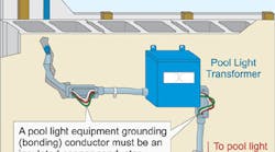
Pool lights. When wiring luminaires in a pool, the goal is to light up the pool, not its occupants. This is why branch-circuit conductors for an underwater luminaire must contain an insulated copper equipment grounding (bonding) conductor sized per Table 250.122. In no case can this conductor be smaller than 12 AWG (Fig. 1).
You must not splice the equipment grounding (bonding) conductor for the underwater luminaire [680.23(F)(2)], unless one of two conditions exists (Fig. 2 on page 46):
-
More than one underwater luminaire is supplied by the same branch circuit. If so, the equipment grounding (bonding) conductor can terminate at a listed pool junction box that meets the requirements of 680.24(A).
-
The equipment grounding (bonding) conductor terminates at the grounding terminal of a listed pool transformer, GFCI, clock switch, or manual snap switch that is located between the panelboard and a junction box connected to the conduit that extends directly to the underwater luminaire.
The branch-circuit conductors for the underwater luminaire must not occupy raceways, boxes, or enclosures containing other conductors on the load side of a GFCI or transformer — unless one of the following conditions exists:
-
The other conductors are GFCI protected.
-
The other conductors are grounding (bonding) conductors.
-
The other conductors supply a feed-through type GFCI.
-
The other conductors are in a panelboard.
Junction boxes. The junction box (deck box) that connects directly to an underwater permanently installed pool, outdoor spa, or outdoor hot tub luminaire forming shell must be listed as a swimming pool junction box and equipped with threaded entries or a nonmetallic hub [680.24]. It also must be constructed of copper, brass, or corrosion-resistant material approved by the authority having jurisdiction (AHJ). You must provide electrical continuity between all metal conduit and the grounding (bonding) terminals within the junction box.
You also must ensure the junction box has at least one more grounding (bonding) terminal than the number of conduit entries [680.24(D)]. Typically, there are four grounding (bonding) terminals in the junction box and three conduit entries. Finally, you must provide a strain relief at the enclosure where you terminate the flexible cord of an underwater luminaire [680.24(E)].
Bonding metal parts to the equipotential bonding grid. Ensure the following five parts of a permanently installed pool, outdoor spa, or outdoor hot tub are bonded together and to the equipotential bonding grid.
-
All metallic parts of reinforcing metal not encapsulated with a nonconductive compound. The usual steel tie-wires that secure rebar together are considered suitable for bonding the reinforcing steel together (Fig. 3 on page 46). Where conductive reinforcing steel of the permanently installed pool, outdoor spa, or outdoor hot tub shell and deck is not available, you must provide an alternative means in accordance with 680.26(C) to eliminate voltage gradients that would otherwise be provided by unencapsulated, bonded reinforcing steel.
-
All metal forming shells for underwater wet-niche luminaires.
-
Metal fittings within or attached to the permanently installed pool, outdoor spa, or outdoor hot tub structure, such as ladders and handrails.
-
Metal parts of electrical equipment associated with the circulating system (water heaters and pump motors) and metal parts of equipment associated with pool covers.
-
Metal cables, metal raceways, metal piping, and all fixed metal parts of electrical equipment — except those separated from the pool by a permanent barrier located within:
-
5 feet horizontally of the inside walls of the permanently installed pool, outdoor spa, or outdoor hot tub.
-
12 feet above the maximum water level of the permanently installed pool, outdoor spa, or outdoor hot tub; or any observation stands, towers, platforms, or diving structures.
The equipotential bonding grid. All metal parts specified in 680.26(B) must be bonded to an equipotential bonding grid with a solid copper conductor not smaller than 8 AWG. The termination of the bonding conductor must be made by exothermic welding, listed pressure connectors, or listed clamps that are labeled as suitable for the purpose. An equipotential bonding grid must extend under paved walking surfaces for 3 feet horizontally from the water [680.26(C)].
The equipotential bonding grid must be formed from either or both of:
-
The structural reinforcing steel of a concrete permanently installed pool, outdoor spa, or outdoor hot tub, tied together by the usual steel tie wires.
-
The metal walls of a permanently installed pool, outdoor spa, or outdoor hot tub.
What if neither of these is available? Where structural reinforcing steel or the walls of bolted or welded metal permanently installed pool, outdoor spa, or outdoor hot tub structures are not available, you must construct an equipotential bonding grid as follows:
(a) The equipotential grid can be constructed with 8 AWG bare solid copper conductors that are bonded to each other at all points of crossing by exothermic welding, listed pressure connectors of the set screw or compression type, listed clamps, or other listed fittings [250.8].
(b) The equipotential bonding grid must cover the contour of the permanently installed pool, outdoor spa, or outdoor hot tub, and deck extending 3 feet horizontally from the water. The equipotential bonding grid must be arranged in a 1-foot by 1-foot network of 8 AWG conductors, with a tolerance of 4 inches.
All equipotential bonding terminations must be by exothermic welding, listed pressure connectors of the set screw or compression type, listed clamps, or other listed fittings [250.8].
Dispelling common myths. Let's go back for a moment to a frequently misapplied term: grounding. One of the myths about grounding (earthing) is that it reduces shock hazards by bringing everything to ground potential. Because the earth is not of uniform conductivity, that can hardly be the case. Another myth is that grounding (earthing) provides a common reference point. This also defies logic.
What about that common reference? If ground (earth) is not it, what is? You can establish a common reference by constructing a bonding grid, not an earthing connection. Connect your bonding path to the grounding grid, and all of the objects are at an equal potential.
When you have equal potential, then by definition you do not have a voltage difference. Without a voltage difference, there can be no current flow. Thus, you use an equipotential bonding system — not a grounding system — to reduce shock hazards.


