As compared to small commercial and residential projects, choosing the appropriate power cable insulation for large industrial installations can be a bit more complex, especially for medium-voltage (MV) applications. For the purposes of this article, MV is defined as 2,001V through 35,000V.
National Electrical Code (NEC) Table 310.104(C) is titled “Conductor Application and Insulation Rated 2,001V or Higher.” For MV solid dielectric cables, there are two basic types of insulation: thermoplastic and thermosetting. Thermoplastic is a heat-resistant plastic compound manufactured from polyvinyl chloride (PVC). Thermosetting refers to cross-linked polyethylene (XLPE) insulation. Both thermoplastic and thermosetting types of insulation have excellent insulating properties and operating temperature ranges. However, thermosetting has a higher safety margin at both ends of its operating temperature range. In other words, it can withstand short durations outside its rated operating temperature better than thermoplastic can.
Thermoplastic materials tend to lose their shape upon post-extrusion heating, whereas thermosetting insulations maintain their form. For instance, during a fault, if a cable experiences a temperature slightly above its rated operating temperature, thermoplastic may soften, causing thin or open areas in the insulation where it is pressed against another conductor, cable tray, fitting, etc. XLPE cable in the same circumstances won’t be as prone to damage.
Another thermosetting material used in MV cable insulations is ethylene propylene rubber (EPR). Made from ethylene, propylene (and, in many cases, a third type of monomer), EPR is used for medium- and high-voltage cable. Note: A monomer can be defined as a chemical compound composed of simple molecules from which polymers can be made. The EPR insulation is typically covered with another material, such as PVC. It can be manufactured as a single conductor wire or assembled as a multiconductor cable. While XLPE and EPR are both thermoset insulations, XLPE is a highly crystalline material, whereas EPR ranges from no apparent crystalline form to semi-crystalline. Thus, EPR has greater flexibility over XLPE.
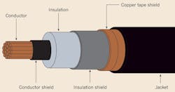
MV cables are typically required to be shielded [see NEC Sec. 310.10(E)] (Fig. 2). MV cables also have insulation category levels of 100%, 133%, and 173%, as defined by the Association of Edison Illuminating Companies (AEIC). Insulation category levels only apply to shielded cables. If the fault clearing time is less than 1 minute, 100% insulation level cable can be used. For a fault clearing time from one minute to one hour, 133% insulation level should be used. And where the fault clearing time is indefinite, a 173% insulation level should be used [See NEC notes to Table 310.104(E)]. This is important to keep in mind, especially where high-impedance grounding systems are used.
Fault currents must be considered, along with ampacity and voltage drop, when choosing an MV cable. NEC Art. 110.10 requires that all circuit components be chosen so that they will not be extensively damaged under fault conditions before the fault is cleared, meaning that cable must be suitable to withstand whatever fault current it’s exposed to. Because faults can induce high conductor temperatures (with the potential to damage conductor insulation) — and sizing a conductor for only continuous ampacity does not consider this — separate calculations must be made when high fault currents may exist. The Insulated Cable Engineers Association (ICEA) has published standards that provide formulae and charts for ensuring cables are properly sized for short circuit protection.
ICEA P-32-382, “Short Circuit Characteristics of Insulated Cable,” provides the foundation for understanding the calculations for short circuit protection of cables and includes simple-to-use formulae and charts. After choosing the correct formula for either copper or aluminum conductors, the insulation type must be considered to determine its maximum operating temperature and maximum short circuit temperature. For example, thermoplastic insulation with a rated maximum operating temperature of 75°C will damage at 250°C under short circuit conditions. Similarly, thermosetting insulation rated for 90°C will have a maximum short circuit temperature of 250°C.
Allowable short circuit currents for insulated conductors
Copper conductor:
Aluminum conductor:
Where:
I = Short circuit current (amperes)
A = Conductor area (circular mils)
t = Duration of short circuit (seconds)
T1 = Maximum operating temperature (°C)
T2 = Maximum short circuit temperature (°C)
Although these formulae appear somewhat complicated at first glance, there are really only three variables:
Allowable (or available) short circuit current;
Conductor size; and
Duration of the short circuit.
T1 and T2 are characteristics of the insulation and should be part of the project specifications. Therefore, only two of the three following items are needed to solve for the other:
Specific conductor size,
Specific short circuit current, or
Specific short circuit duration.
A common approach is to solve for the conductor area required to withstand the available symmetrical interrupting short circuit current and the upstream breaker clearing time, which must account for both the relay pick-up time and the breaker operating time (both of which are available from the respective manufacturers). After solving for the minimum required conductor area, compare this value to the cable size chosen based on ampacity, and confirm that the conductor is large enough for both. Let’s run through an example to help drive these points home.
After checking the ampacity and voltage drop for a feeder, a 250kcmil CU conductor is chosen. Will this conductor sustain insulation damage during short circuit? These initial data points are available to us.
• A short circuit study results in a maximum available interrupting current of 45kA (symmetrical).
• The protection relay guarantees a signal within three cycles for short circuit pick up. The upstream breaker is a five cycle ANSI type. The total clear time is eight cycles, which at 60 Hz equals 0.133 seconds.
• The cable has copper conductors with thermoset insulation rated 90°C maximum operating temperature and a 250°C maximum short circuit temperature.
Since the available short circuit and the clearing time is known, this may be calculated in one of two ways:
1) Solve for the minimum conductor size using 45kA for short circuit and compare to a 250kcmil, or
2) Solve for the maximum short circuit current that a 250kcmil conductor is suitable for and compare to 45kA.
Choosing method (1) and using the equation for copper conductors results in this equation:
Solving this equation results in A = 228,379 circular mils. This is the minimum conductor size required in this specific application. Therefore, the 250kcmil conductor is adequate to withstand the short circuit conditions in this case without damage.
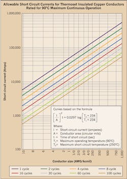
Figure 1 is taken from ICEA P-32-382 for maximum allowable short circuit currents for copper conductors insulated with 90°C rated thermoset insulation. Also note that the cycle time is for a system operating at 60 Hz. The formula is the best way to confirm cable suitability, but if the conductors match the parameters of a chart, it can be useful to determine if the conductor is close to its limit or obviously in a safe zone.
In addition to performing calculations to confirm that the conductor will be suitable to withstand the available short circuit current, it may also be necessary to confirm that the metallic shield is sufficient to carry the calculated available ground fault current that it will see during short circuit conditions. ICEA P-45-492, “Short Circuit Characteristics of Metallic Shields and Sheaths on Insulated Cable,” addresses how to calculate the required cross-sectional area of metallic shields. This publication contains formulae that allow calculation of either maximum permitted short circuit current, required shield area, or maximum short circuit current duration, just as P-32-382 does for conductors.
Editor’s note: The Figure is reprinted with permission from ICEA. This edited version is different from the original. ICEA Standards are subject to periodic review and revision. This article, other than the ICEA table, is copyrighted by Fluor Corp. © 2016 Fluor Corp. All Rights Reserved.
Guidry is a technical director at Fluor Enterprises, Inc., Sugar Land, Texas. The majority of his 38 years of experience includes upstream and downstream portions of petrochemical plants and refineries. He is also heavily experienced in water and wastewater treatment facilities. He can be reached at [email protected].
