“Use it, or lose it” applies to everyday life in many ways. In the electrical trade specifically, not performing certain skills for some time (or with little frequency) means we become rusty. Given the variety of our day-to-day work environments, not all electrical professionals are exposed to skills outside of the job they normally perform. Few things in the field are more frustrating — and potentially more dangerous — for an electrical worker than not having a handle on the following key skill areas. Staying sharp in these five areas keeps work professional, increases safety, and makes you comfortable in your job.
Multimeter usage
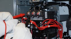
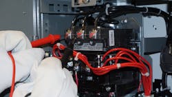
The multimeter is merely an extension of an electrical worker’s hand (Photo 1). It can touch energized equipment and tell the condition/status of electrical equipment like no other tool in the pouch. When misapplied or misused, however, it can become deadly. Proper use and interpretation of multimeter readings are at the core of basic skills for the electrical worker.
Digital multimeters (DMMs), including test leads that must be properly rated for the application, must be clearly marked with the appropriate voltage rating, applicable current ratings, and the proper Category rating. Always verify the appropriate Category rating (i.e., voltage surge capacity) of the meter for the task at hand.
DMMs can only be used by qualified persons, whether measuring energized circuits or verifying circuits are de-energized when performing a lockout/tagout procedure. Test equipment must be inspected before each use. A meter that was safe at the beginning of one shift is not guaranteed to be safe for placing on a live circuit a few hours later. Inspect the meter for signs of physical damage and proper ratings. Be sure to include test leads, probes, and any accessories you may anticipate using, such as clamps or alligator clips designed for usage on test probes.
Verifying a circuit is de-energized is one of the most important uses of a DMM. Failure to perform this operation correctly has been known to result in fatalities. Always perform a live-dead-live test. Make sure the meter works properly on a known voltage source, verify zero volts on the circuit under test, and then verify the meter still works properly. Review the NFPA 70E standard if you are not comfortable with this three-point method. Spend time learning the varied functions of your DMM before using it in the field.
Conduit installation
For the maintenance electrical technician, conduit runs are typically not "run of the mill" as they are in the construction field. The maintenance technician may go for years without having to install conduit. Then, one day, he’s suddenly asked to install or replace equipment.
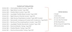
First, recall that the requirements for conduit and cables are found in Chapter 3 of the NEC. Each conduit type or cable type has its own separate Article.
Suppose the maintenance technician is asked to replace a small motor (Photo 2). Perhaps this work calls for a new piece of flexible conduit to be installed. The questions might become:
- "What type and size of flexible conduit can be used?"
- "Do I need to support flexible conduit?"
- "I have seen the green insulated equipment grounding conductors run on the outside of this conduit. Will I run that wire the same way in this application?"
These questions, if not properly answered, could result in a non-compliant and unsafe installation — not to mention the technician will experience that uneasy feeling of not quite remembering where to locate the NEC information to answer these questions.
Make work easier and less frustrating by referring to the information in Fig. 1. Of course, NEC knowledge is always required for electrical work. All the conduit and raceway Articles use the same numbering format. Thus, if using liquidtight flexible metal conduit (Type LFMC) as in the above example, then refer to Art. 350 for the answers. Section 350.22 points the worker to the correct Tables in the NEC for sizing the conduit. Section 350.30 addresses securing and supporting requirements. In fact, the maintenance person may find some helpful information in Exception No. 2 to keep the support requirements practical. Equipment grounding conductor (EGC) installation is covered in Art. 250 [Grounding and Bonding].
Cutting, bending, and installing conduit must be done in a neat and workmanlike manner. The NEC provides an important Informational Note in Sec. 110.12 [Mechanical Execution of Work]. The ANSI/NECA 1-2015 Standard provides the accepted industry practices for electrical installation work.
Various job aids, texts, and videos are available to help with conduit bending and installation. Set up a training area in the shop to keep bending skills sharp. A few sticks of conduit to bend now, which help ensure neat and workmanlike compliance, is probably cheaper than a big scrap bin.
Safe work practices
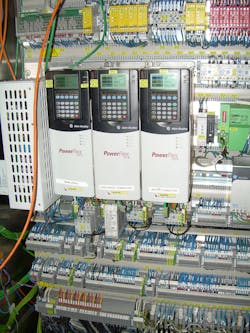
Because of regulatory, technology, and cultural changes, electrical workers are better protected today than they were just a few years ago. However, the mass of information available and complexity of equipment can be confusing (Photo 3). Here is an overview of the safe electrical work practices you should follow to stay safe. Of course, always follow company procedures as well.
- Assess the risk. The two primary concerns regarding electrical hazards are electric shock and burn (review NFPA 70E, Standard for Electrical Safety in the Workplace). When assessing any risk, consider the likelihood of an incident occurring and — should it occur — the possible severity of the injury or damage to health. Documenting the risk assessment is a must. Most organizations use a job safety analysis (JSA) or job hazard analysis (JHA) to plan and conduct all work. Job safety planning for electrical tasks is often not fully addressed in existing JSAs or JHAs. Consider revising these documents to properly address shock and burn, or use a separate electrical job safety plan. Arc flash warning labels provide minimum requirements. Take additional precautions when needed.
- Select and inspect personal protective equipment (PPE). Insulating rubber gloves must be inspected daily before use. Perform a visual inspection, looking for signs of physical damage, dates within compliance, and pass a field air test. Make sure the leather protectors are free from physical damage and of the correct length and glove size for the rubber gloves being used. Arc-rated clothing must have an ATPV rating equal to or greater than the incident energy on the arc flash warning label. Refer to NFPA 70E for additional PPE that must be used, such as hearing protection, hard hats, leather footwear, safety glasses, and other items as needed.
- Establish checklist. Before operation of electrical equipment, including opening doors for access, certain items for normal operation of equipment must be verified. For example, the equipment must be installed properly. Perform a visual inspection, and refer to drawings (if necessary). Verify the equipment has been properly maintained by reviewing maintenance records.
- Set up a barricade. The objective is to prevent other persons from receiving burns or being shocked. The Limited Approach Boundary is based on voltage levels taken from tables found in NFPA 70E. A shock hazard is considered to exist within this boundary. An Arc Flash Boundary is where the incident energy levels drop to the onset of a second-degree burn. Because people must be protected from both shock injury and arc flash burns, a physical barricade is set up at the Arc Flash Boundary or the Limited Approach Boundary, whichever is greater.
- Follow safe work practices to do the work. Establishing an electrically safe work condition is always the best option. Follow the steps of your hazardous energy control (electrical lockout/tagout) procedure to create an electrically safe work condition. Refer to the definition of "Working On" in NFPA 70E to help determine the need for an Energized Electrical Work Permit. Repair work requires this document ― which includes using an insulated screwdriver to tighten a terminal screw. Always de-energize if possible, know the equipment conditions considered necessary for normal operation, and follow your organization’s safe work procedures. Above all, exercise electrical common sense. Humility is always the biggest part of electrical safety. If there is any doubt, stop work and ask for help. Take refresher training courses on electrical safety and provide input to your company electrical safety policy. Be an electrical safety champion for your organization.
The National Electrical Code
We sometimes hear people say: “But the NEC does not apply to maintenance work.” This is false. Just as wrenches and screwdrivers are tools used in construction and maintenance, the NEC is a tool that provides the knowledge requirements for electrical installation and maintenance activities.
The purpose of the NEC is safety. The very beginning of the Code states the purpose is “… the practical safeguarding of persons and property from hazards arising from the use of electricity.” The very next subsection points out the necessity for “proper maintenance” to help keep those hazards of electric shock and fire in check. Oftentimes, maintenance is performed with little thought to NEC requirements.
Replacing existing electrical equipment and devices are typical maintenance tasks. The previous example of the flexible conduit installation points out the need for basic Code knowledge for the maintenance electrician. Be sure to follow your organization's electrical installation requirements (if available), and, as always, remember that the AHJ has the final say.
First, be aware that the NEC does make some provisions for existing installations. For example, if replacing a panelboard across the aisle from a switchboard in an older facility, it is possible to reduce the clearance distance requirements between the two by 6 inches. However, pay attention to the details. Getting an extra 6 inches of clearance distance requires written procedures to ensure both pieces of equipment are not open at the same time — and only qualified persons are authorized to work on the equipment. Pay attention to details in the Code.
AFCI and GFCI requirements continue to change with updated editions of the Code. For example, installing a 240V circuit for a clothes dryer in a laundry room now requires GFCI protection for the receptacle. In fact, all single-phase 250V receptacles in the locations specified in the NEC now require GFCI protection. Also, rules for GFCIs are not just found in Sec. 210.8 for ground-fault circuit-interrupter protection for personnel. GFCI requirements for certain appliances are found in Art. 422. Swimming pools, storable pools, spas, and hot tubs have GFCI requirements found in Art. 680. Searching the index of the NEC shows GFCI requirements scattered throughout 23 separate Articles.
The purpose of the motor overload relay is to prevent motor overheating, equipment damage, and possible fire. Overload relay settings are found in the NEC. Typical overload settings are 115% or 125% of the nameplate full-load current rating of the motor. In some cases, this setting can be as high as 140% of the full-load current. Always consult the NEC and manufacturer's instructions when conducting motor maintenance.
Electrical maintenance and construction work must be done properly to maintain a safe electrical installation. The NEC changes every three years. Use training and other resources to stay on top of the areas in which you work, and refresh yourself on Articles you may only occasionally use.
Sharpen troubleshooting skills
Troubleshooting electrical control circuits requires specialized knowledge and technique. Trying to step your way through a ladder diagram without knowledge of the symbols and how the drawing is designed to show operation of the circuit will lead to a long, frustrating, and (most likely) non-productive troubleshooting experience. In fact, jobs will quickly come to a grinding halt if workers fail to develop the proper troubleshooting skills.
NEMA symbology must be second nature to the electrical troubleshooter. Yet, IEC controls and circuitry are the standard for much manufacturing equipment, thus requiring even more knowledge. Once proficiency is developed in reading and interpreting these specialized diagrams, proper operation of the circuit can be verified using the multimeter. If not operating properly, the real process of troubleshooting begins.
First, put electrical common sense to work: Look and smell for signs of overheating. Is there an emergency stop that was accidentally pushed and not reset? Is something mechanical slightly out of position, preventing a limit switch from operating properly? If all appears normal, it is time to gather up the prints and the DMM. Follow all safe work practices, and begin a logical, systematic approach to troubleshooting.
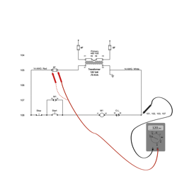
Let’s run through an example using Fig. 2 below. First, trace voltage through the circuit following the flow path. Is there incoming power? If not, head upstream to find out why. If the incoming power is at the correct voltage, then place one test lead on ground, and begin looking for the "missing voltage." For instance, with one lead on ground, place the other lead at the line side of the control power fuse. If there is voltage on the meter, then take the test lead and place it on the load side of this fuse. If there is no voltage present at this point, then the fuse is open. Continue this process, moving down through the circuit. For ladder diagrams, it is generally best if read from top to bottom and left to right across each rung.
Once this technique is understood, hours of troubleshooting or "Easter egging" can be eliminated. The goal for much electrical maintenance work is to reduce downtime — whether it is a rooftop unit, an injection molding machine, or an air compressor in someone's garage.
Reading and interpreting electrical diagrams is the starting point for most electrical troubleshooting tasks. Becoming a successful troubleshooter means establishing a logical and systematic approach looking for that electrical control problem. Once this approach is practiced and applied, you become better and better at finding control circuit problems quickly and efficiently. Less downtime means satisfied operations personnel and clients. Practice reading schematic diagrams, and develop a logical and systematic approach to troubleshooting.
On top of your game
Electrical jobs are vast and varied. No one electrical worker can be the expert in all areas of electrical construction and maintenance. However, proper use and interpretation of meters, the ability to correctly and professionally install conduit and raceway systems, following safe electrical work practices, knowing how to apply information found in the NEC, and developing a systematic approach to troubleshooting all combine to help electrical workers build a sound foundation.
The bottom line is work safely, train, and practice the skills of the trade you may not use that often to stay on top. Consider establishing a training area in the shop to practice. Sharpen your skills, and conduct training to refresh your knowledge. That way, you’ll stay at the top of your game and not fall victim to the real-world consequences of losing your skills if you don’t use them.
Barnett is electrical codes and safety program manager for NTT Training, Centennial, Colo. He can be reached at [email protected].
![Photo 2. Conduit runs must be installed per the NEC requirements ― even short runs of flexible conduit. This liquidtight flexible metal conduit (Type LFMC) is not supported within 12 in. of its termination points. However, Exception No. 2 in Sec. 350.30 of the NEC [Securing and Supporting] can be argued as an exception in this case and was approved by the authority having jurisdiction (AHJ). Photo 2. Conduit runs must be installed per the NEC requirements ― even short runs of flexible conduit. This liquidtight flexible metal conduit (Type LFMC) is not supported within 12 in. of its termination points. However, Exception No. 2 in Sec. 350.30 of the NEC [Securing and Supporting] can be argued as an exception in this case and was approved by the authority having jurisdiction (AHJ).](https://img.ecmweb.com/files/base/ebm/ecmweb/image/2021/04/Photo_2.606b31fbe87fc.png?auto=format,compress&fit=max&q=45&w=250&width=250)
