A multimeter and its test leads allow electrical workers to reach into an energized panel, touch live circuit components with the end of the test leads, and capture electrical readings like voltage, current, and resistance. A multimeter can also be used to determine if a particular circuit is open or has continuity. In some applications, you can measure frequency and even temperature. Yet, if not used effectively, inaccurate readings result in a failed diagnosis. Or, worse yet, misapplication can result in costly, or even deadly, consequences. See the Sidebar below on “Ten Deadly Mistakes to Avoid When Using a Multimeter.” Effective use of the multimeter is a worthy professional goal for all electrical workers.
Analog or digital?
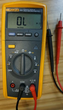
Two basic types of multimeters are in use today — the analog multimeter and the digital multimeter (DMM), as shown in Photo 1. Although the digital version is by far the most used type, the competent electrical professional needs to be comfortable with analog meters, too.
The first practical electrical meter for its time, the galvanometer appeared in 1820 and measured current only. It was a hundred years later when a British engineer developed a meter that could read amperage, voltage, and resistance. Until the 1970s, these meters were analog meters.
The analog meter uses a needle to move across a scale on the face of the meter. It responds quickly to input changes, and watching the movement of the needle often provides for easy interpretation of changing values. Even though DMMs typically have a bar graph across the bottom of the display to provide an analog indication, the continuous movement of the analog meter needle is preferred by some technicians in certain applications.
When using analog meters, care must be taken to avoid parallax error. You must read directly over the needle to obtain an accurate reading.
TIP #1: Parallax error occurs if the indicating needle is observed at an angle to the meter face. To avoid parallax error when using an analog multimeter, it is advantageous to use a multimeter with a small mirror on the meter face. The correct reading is observed when the indicating needle appears directly over its reflection in the mirror.
In the late 1970s, DMMs began appearing in the market. Electronic technology greatly simplified measurement and testing. With the digital readout on the meter face, accuracy significantly improved.
For the user in the field, the single biggest advantage of the DMM is ease of use. These devices are easily carried, rugged, reliable, and simple to use. However, the user must understand each multimeter function to be most effective.
All multimeters measure voltage, current, and resistance. Some offer more specific functions and features, such as the ability to measure frequency, capacitance, and even temperature. Additionally, modern DMMs are auto-ranging. Rather than selecting the appropriate range on a selector switch for the values to be observed, the meter automatically detects the voltage, current, or resistance value and selects a range for the measurement. DMMs may also have the option to manually select the desired range. However, those operating the DMM must be comfortable selecting the correct meter function and understand the various indications on the meter face.
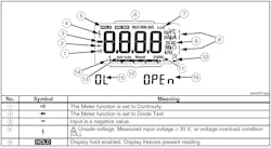
TIP #2: Familiarize yourself with your multimeter functions, capabilities, and ratings before usage. In the field, effective multimeter use should be second nature to the electrical worker (see manual diagram below).
Do I need a true RMS multimeter?
Effective multimeter use includes selecting the correct meter type based on the sine wave characteristic to be measured. Therefore, using an average responding meter when a true root-mean-square (RMS) meter is needed will result in an inaccurate reading. Average responding meters provide the most accurate readings when measuring pure (clean) sine waves. If the sine wave is distorted, then the true reading meter will be the most accurate. It is common for sine waves to be distorted in a distribution system due to power quality issues. Additionally, the output of electronic drives (i.e., VFDs and VSDs) is a series of pulses that can only be accurately measured with a true meter.
DMMs may have “true RMS” identified on the meter, which can be confusing. All DMMs measure RMS values. For example, a meter that reads 480VAC is reading the RMS value of the peak of the sine wave. The peak value of 480VAC is 679VAC [480VAC(RMS) × 1.414 = 678.72VAC(peak)]. This is important for the technician to realize from a safety standpoint. Placing test leads on 480VAC terminals, for example, is actually putting you in contact with a peak value of 680V — considerably more electromotive force.
TIP #3: Using a true RMS meter is an industry best practice in commercial and industrial applications. From laser printers and copy machines to variable-frequency drives and forklift battery chargers, these electronic-driven types of equipment will cause distortion of the clean 60 Hz sine wave. Make sure you know your distribution system.
Selection and inspection
Like choosing any tool for the job, consider the task at hand, and ask the right questions when it comes to multimeters. What is the nominal voltage level of the system to be measured? Is it AC only or both AC and DC? How important is accuracy? Is the meter to be used for general purposes, such as verifying the presence or absence of voltage? Must amperage readings for motors or other equipment be measured? In short, what are the required functions and meter capabilities?
NFPA 70E, Standard for Electrical Safety in the Workplace, devotes a section to safety requirements for test instruments and equipment. Perhaps the most important requirement is that only qualified persons perform testing, troubleshooting, and voltage measurements on equipment if the worker is exposed to an electrical hazard. While the 70E standard defines and explains training requirements for qualified electrical workers, the short story is workers must demonstrate their skills and knowledge related to their equipment and receive safety training on how to recognize and mitigate hazards.
When it comes to the effective use of the multimeter, safety must not be ignored. Multimeter remote displays and Bluetooth capability have only added to safer meter usage. When it comes to performing tests and measurements, a near-miss is not acceptable. Workers will have their fingertips, even though wearing insulated rubber gloves, within an inch or less of a live terminal when measuring voltage. Faulty meters and improperly applied meters have caused serious, and even fatal, incidents. Do not take chances!
TIP #4: Make meter inspection and proper usage a habit. Use the Sidebar below, “Meter Safety Inspection Checklist,” as an outline for a safety meeting. Have workers bring their multimeters to the meeting, and conduct the safety inspection outlined.
Like all electrical equipment, multimeters must be properly rated for the values they will measure. Review the multimeter manual to determine these values, including amperage ratings. When using the meter in series with the circuit to measure amperage, the meter is typically protected by a fuse to prevent damage should the meter amperage rating be exceeded. If the circuit resistance is greater than what the DMM can measure, “OL” will appear on the display (indicating overload).
Measuring voltage
Measuring voltage involves measuring the difference in potential between two energized points in a circuit or measuring the difference in potential between one ungrounded energized test point and ground. The function switch must be set to AC or DC as appropriate.
TIP #5: A small stray (ghost) voltage may appear on the display when attempting to measure the voltage on de-energized terminals, even when the test leads are not applied to any terminal points. This phenomenon, which is normal, is due to meter design.
The typical DMM is rated at 1,000V maximum. In other words, the meter should never be applied to a circuit where the nominal voltage rating of the circuit exceeds 1,000V. Unfortunately, there have been fatalities for violating this rule.
The nominal voltage rating of a circuit is an assigned value. In reality, AC distribution systems will incur many transient voltage conditions during normal operation. The voltage will spike for just a fraction of the cycle at well over 1,000V — even in residential circuits. To provide protection against these transient conditions, DMMs also have a “Category Rating” to reflect their ability to withstand transient voltages. These voltage spikes will be more severe the closer the measurement is taken to the outdoor portion of the system. For most cases, this would be an electrical service — the point at which the electric utility supplies power to the premises wiring system. However, overhead feeders are also an example. The key is to make sure the meter has the proper Category (CAT) rating for the location in the system where the multimeter will be applied.
TIP #6: There are four CAT ratings for DMMs. Typical applications for each category are CAT I — for use on protected electronic equipment; CAT II — for use on outlets on a branch circuit; CAT III — for use on fixed equipment (e.g., motors, lighting, etc.); and CAT IV — for outside and at service entrances. Typical DMMs are often rated for CAT IV 600V, and CAT III 1,000V. Typical applications would be using this meter to measure incoming 480V at the service or incoming outdoor feeder and then using it for any work inside the facility on equipment rated up to 1,000V.
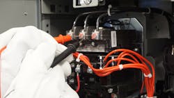
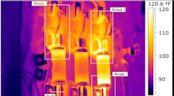
TIP #7: When troubleshooting and tracing voltage through a circuit, make sure you understand the operation of basic circuit components (Photo 2). For example, reading across a set of open contacts will measure the system voltage; reading across a set of closed contacts should read 0V. Any voltage measured across closed contacts typically indicates dirty contacts.
Measuring resistance and “ringing out a circuit”
Measuring resistance values can easily be done with a DMM. The unit’s battery pushes current flow through one meter lead and into the circuit. The current then flows from the circuit into the opposite test lead and back into the meter battery. The meter is designed to analyze the amount of current that flows through the circuit and display the resistance reading in ohms, kilohms, or megaohms, as applicable.
TIP #8: Always verify a circuit is de-energized before measuring resistance. DMMs have protective circuitry, and some may indicate the circuit is energized if attempting to read resistance. However, attempting to apply low-voltage DC batteries found in multimeters to an energized 120VAC circuit or above is never a good idea.
While actual resistance values are sometimes needed, troubleshooting is often accomplished by testing for continuity. The term “ringing out the circuit” most likely evolved when some of the first continuity testers used a battery and doorbell in series with the circuit under test. If there was a complete path of current flow from the battery, through the circuit and doorbell, and back to the battery, then the bell would ring, indicating continuity. Today’s DMM provides both visual and audible indications.
TIP #9: Hearing the meter’s audible sound may be difficult in many settings. Consider using a magnetic hanger accessory to conveniently place the meter near the circuit under test and easily observe the measured values as both hands will be occupied with test probes.
TIP #10: One method to ring out a cable is to twist one pair of wires together at one end and test wires at the opposite end for continuity. The two that are twisted together at one end will read continuity at the opposite end. The same results can be achieved by connecting one wire to ground at one end (using a simple jumper wire with alligator clips). Then the wire at the opposite end will read continuity when tested to ground. Be sure to label wires as you go.
Measuring current
There are two methods to measure current with the multimeter. The first method places the multimeter in series with the circuit. This method, though not often used, can be of value when troubleshooting or calibrating low-amperage circuits. Such meter functions typically have a range of up to 10A.
To measure current when using the multimeter in series with the circuit, first ensure the circuit is de-energized. Plug the black test lead into the common jack. Plug the red test lead into the amperage or “A” jack. Set the meter function to the amps AC or DC setting as appropriate. Using alligator clip accessories on the test leads is often best for securing test leads in place. Energize the circuit, and the amperage value appears on the display.
TIP #11: If DC current or voltage is measured and a negative sign appears to the left of the indicated value, the meter leads are reversed in the circuit. The reading obtained is still accurate, and there is no need to de-energize the circuit and reverse the test leads.
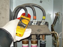
Using the clamp function of the DMM is the most practical method for the more common amperage measurements needed. Determining the current draw of a motor or troubleshooting overload conditions in a panelboard are common uses of the DMM clamp, which in and of itself can either be a part of the meter or can be purchased as a separate attachment.
TIP #12: Take precautions anytime the clamp function is used to measure amperage. “Probing” with a clamp on the end of a meter — pushing the clamp through and around energized conductors in a circuit — is not a safe activity. Loose terminations can result in conductors being knocked loose from their terminations, creating severe shock and arc flash hazards. Always make a good visual inspection of the enclosure before applying a multimeter clamp. Flexible clamps are also available.
TIP #13: Clamp-on ammeter readings can only be accomplished by clamping around one conductor at a time (Photo 3). Otherwise, only zero will be displayed in single-phase circuits and in 3-phase circuits where all three conductors are inside the clamp at the same time.
Summary
Effective use of the multimeter requires familiarity with the meter itself. Whether digital or analog, electrical workers should spend time reviewing the multimeter manual and become knowledgeable of the various meter functions and capabilities. Measuring resistance always requires a circuit to be de-energized. Safety includes a daily check before use of the multimeter, including the meter test leads. Measuring voltage and using a clamp function for amperage requires work on energized circuits. Be sure to follow all safety precautions outlined in company procedures and the NFPA 70E standard. Effective measurements are a combination of multimeter capability (including ratings, user knowledge, technical expertise, and safe work practices). Always strive to improve your skills and knowledge when it comes to effective use of the multimeter.
Randy Barnett is a certified electrical safety compliance professional (CESCP). He can be reached at [email protected].
SIDEBAR 1: Multimeter Safety Inspection Checklist
- Verify voltage rating appropriate for nominal voltage.
- Verify proper category rating for use.
- Verify meter is suitable for the environment where it will be used.
- Visually inspect for external defects or damage (including any accessories to be used for measurements).
- Verify no “low battery” warning.
- Inspect test leads for any signs of physical damage.
- Inspect test leads for proper rating — as a minimum at least the same as the multimeter ratings.
- Measure resistance of test leads (typically 0.1 to 0.3 ohms on a DMM; 0 ohms, or adjust to zero on analog meters).
- Verify meter operates on a known voltage source (AC or DC).
- Verify only qualified persons will measure voltage or current with the multimeter.
SIDEBAR 2: Ten Deadly Mistakes to Avoid When Using a Multimeter
- Failure to inspect before use.
- Improper care and storage.
- Use on a system with a higher nominal system voltage than the rated multimeter voltage.
- Using damaged test equipment (once sent this author to the hospital!).
- Choosing a multimeter with the wrong category rating.
- Selecting the wrong function option on the meter.
- Incorrectly measuring voltage by dragging leads from one terminal to the next as opposed to deliberately first pulling the test lead out and away from the circuit, then placing the test lead onto the next terminal. Failure to follow this best practice can result in an arc flash.
- Using faulty or improperly rated test leads.
- Attempting to read resistance on an energized circuit.
- Failing to use an intrinsically safe DMM when taking measurements in hazardous (classified) locations.
