In a perfect world, electrical insulation would allow no current to flow through it. Unfortunately, several factors can — and will — result in the deterioration and ultimate failure of electrical insulation over time. Excessive heat or cold, moisture, dirt, corrosive vapors, oil, vibration, aging, and damaged wiring can all compromise an insulation system. Faulty insulation can result in equipment underperformance and downtime, as well as pose a danger to personnel.
To assess and monitor insulation integrity, several tests have been developed. These typically involve injecting a test voltage and then measuring the current. Given these two values, resistance can be calculated using Ohms law [R = E/I]. This “stress tests” the insulation in a similar way that applying high water pressure to plumbing systems tests for leaks.
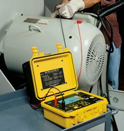
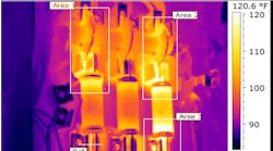
A regular program of resistance testing can detect insulation deterioration so it can be addressed before it becomes a major problem (Photo 1). Insulation resistance testing helps ensure personnel safety and optimal operation of equipment. It also helps evaluate the quality and level of repairs that may be required before equipment is put back into operation.
There are three commonly used methods for testing insulation resistance: spot reading test, time resistance test, and step voltage test. These three tests are used primarily to test insulation in motors, generators, cables, transformers, and other electrical apparatus. Additionally, there are two ratio test methods that are also helpful when testing rotating machinery, such as motors and pumps.
To perform these tests, it is best to have a megohmmeter with a timed test function and the ability to select from a range of test voltages. It is also helpful to have a thermometer or similar temperature measurement device on hand. If the equipment temperature is below the dew point, a humidity measuring instrument will be necessary, especially when performing a spot test.
Safety
Before performing any insulation resistance test, be sure to observe the following safety measures as well as any additional guidelines specified in the documentation that comes with your test instrument, the local safety procedures of your organization, and the facility you are testing at. Insulation resistance testing involves the application of high DC voltages. Properly preparing the system under test and the instrument used to conduct the test are crucial to your safety and help prevent damage to your wiring and machinery.
- Take the equipment under test out of service. Shut down the apparatus, open all switches, and de-energize the unit. Disconnect from all other equipment and circuits, including neutral and protective ground connections. Be sure to follow any applicable lockout/tagout (LOTO) procedures required during this step.
- Perform a thorough inspection of the system. In general, the more equipment included in a test, the lower the resistance reading. Therefore, it is critical to inspect the system and understand exactly what you're including in the test. Make note of any equipment that might be damaged by high test voltages, and either adjust the test voltage accordingly or exclude these components from the test.
- Discharge capacitive build-up before conducting an insulation resistance test. Note that modern megohmmeters automatically discharge this build-up when not running a test if the leads are connected to the device.
- Check current leakage at switches and other connections.
When performing the test, restrict personnel access to the test site. Also, be sure to use personal protective gear such as gloves, safety glasses, and other protective equipment (where appropriate). After the test is complete, make sure the system under test is fully discharged. A minimum discharge time of four to five times the duration of the applied test voltage is recommended. As previously stated, some insulation resistance test instruments include a built-in feature to ensure a safe discharge after the test.
The testing process
Three electrical current components involved in an insulation test need to be understood when conducting a test.
To properly interpret test results, it’s important to understand that the total current flowing through the insulation consists of these three components: capacitance charging current, absorption current, and conduction or leakage current.
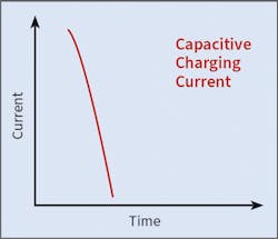
Capacitance charging current
To ensure your results are valid, spot testing should ideally only be performed on systems with temperatures exceeding the dew point. If tests are performed at different temperatures, carefully record the temperature of each test, and apply the appropriate correction to determine what the resistance would be if the test were performed at 20°C (68°F).
Time resistance test
Another insulation resistance measurement method is the time resistance test. Typically, this test method is referred to as the dielectric absorption (DAR) or polarization index (PI) test, depending on the length of test time. It involves noting and recording at least two readings during the test.
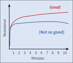
For a DAR test, it is typically the resistance measurement taken 30 seconds into the test and the measurement taken one minute into the test. For a PI test, it is typically the resistance measurement taken one minute into the test and the measurement taken 10 minutes into the test. The ratio is then calculated by dividing the second reading by the first reading to determine a ratio. The higher the ratio, the better the insulation. In newer test instruments these readings are automatically noted and the ratio automatically calculated and displayed. Although DAR is no longer commonly used with newer insulation systems, it still has applicability when testing older insulation materials and/or materials that have a PI ratio of less than 2.
Plotting timed test results if readings are recorded all during the test is also very beneficial. You should see a curve that rises relatively rapidly at first, and then continues to gradually rise throughout the testing period (Fig. 6). If the curve is relatively flat or begins to turn down as the test progresses, moisture, dirt, or other factors may be compromising your insulation.
Time resistance tests on large rotating electrical machinery, especially systems with high operating voltage, require high insulation resistance ranges and a very constant test voltage. Since this test provides meaningful results within the time duration, it is relatively independent of temperature. It is also independent of the size of the system under test.
Step voltage test
A third method is the step voltage test. This involves testing at multiple test voltages and comparing the results. The test begins at an initial test voltage. At a specified interval, typically one minute, a measurement is recorded, after which the test voltage is increased. This process is repeated through several steps, with measurements taken after one minute at each step. A common practice is to test at five voltage steps.
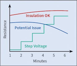
The step voltage test is designed to create electrical stresses on internal insulation cracks, identifying potential problems that may not be revealed by testing at lower voltages (Fig. 7). Insulation that is thoroughly dry, clean, and in good physical condition should provide roughly the same resistance measurements across the voltage range. If you observe a significant decrease in resistance at higher voltage, your insulation may be contaminated or deteriorating.
Step voltage testing is also often used to dry wet cables or equipment. Gradual voltage steps, applied for increasingly longer durations, can facilitate drying through heating.
In summary
Insulation resistance testing is easy to perform correctly once you understand the basic principles. Some devices have mostly resistive characteristics and can be tested quickly using the spot test method. Comparing the test results to previous tests will give you a trend that is valuable in determining the possible need for preventive maintenance. Remember that temperature plays an important role in obtaining the proper results.
Larger equipment, such as motors, pumps, and long cable runs, have inductive properties that need to be considered when testing insulation resistance. The timed test method (along with the ratio tests of DAR and PI) are best used to achieve an accurate indication of the health and quality of the insulation. Capacitive and absorption currents must be dissipated, which takes time, before you can get the actual leakage current measurement needed to calculate insulation resistance. Although these tests take longer to perform than the spot test method, they have the advantage of being independent of the temperature to provide accurate results.
Step voltage testing is like timed testing with the advantage of not over stressing sensitive equipment by gradually applying the test voltage. For your own safety, always remember when doing a timed test to allow the discharging to take place before you remove the test leads.
An understanding of these fundamental requirements will ensure that you perform the test properly, complete the job with confidence, and stay safe in the process.
What to Consider When Purchasing an Insulation Test Instrument
If you are considering purchasing a new megohmmeter, here are some points to consider.
Voltage requirements:
- Plan for the highest voltage you need.
- Consider multiple range instruments; it will give you more flexibility.
- Consider the voltage generation method (hand-crank, battery operated, AC/DC powered). For long test times, AC/DC-powered instruments are best.
Resistance measurement capability:
- Consider a meter that can measure into the Tera Ohm range.
Test current:
- IEEE recommends the availability of 1mA of test current and the ability to hold the test voltage throughout the total test time for valid test results.
- Short-circuit current should be two to three times the available test current to accommodate testing equipment with higher inductive properties in shorter time.
Safety conditions:
- Should function as a voltmeter when not performing an insulation test.
- Should automatically discharge the device under test.
- Should inhibit the test if live voltage detected.
- Test leads should be rated for the test voltage.
- Output should be fused.
Other features:
- Ability to do timed tests.
- Automatic calculation of PI and DAR ratios.
- Automatic display of discharge voltage.
- Display capacitance and leakage current values.
- Ability to automatically conduct step voltage testing.
- Back lighting.
- Ability to configure instrument, run tests, and generate reports from a PC.
Olobri holds degrees in both electrical and industrial engineering and has worked in the design and marketing of instrumentation for more than 35 years. For the past 25 years, he has been with AEMC Instruments, headquartered in Foxborough, Mass., where he has been actively involved in the areas of insulation resistance testing, ground resistance testing, power quality testing, data logging, and environmental testing. He also conducts accredited seminars and webinars on ground resistance testing and insulation resistance testing. He can be reached at [email protected].
