Sure, you’ve got a magnetic personality and can charm customers into expanding the scope of the original project into what they really need done so their equipment is reliable. It doesn’t hurt that this improves your bottom line, as well as theirs. But that’s not the kind of magnetism we’re talking about here.
In a previous Basic Training article, we discussed electromagnetism and touched on how it matters in a practical sense for your daily work. But there’s more to the story.
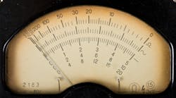
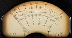
An example older electricians remember from early in their careers is the magnetic meter movement in their portable analog volt-ohm meters. Today, we use digital multimeters (DMMs) instead of those analog volt-ohm meters. But you can still find analog meters in panel displays and in some test equipment.
Basically, the needle on the display is attached to a magnet that moves in response to a small current in the instrument. That meter movement uses electromagnetism somewhat the way an industrial motor does (more on that, in a bit). Let’s look at another way this principle is used in portable meters.
Suppose you desire to measure current with your DMM. It’s got a 2A fuse on the current input, but you’re working with a circuit on which you expect to measure 150A. The solution is a current clamp that’s designed to work with a DMM. Part of this DMM accessory acts like a transformer (another application we’ll look at momentarily).
You select the current clamp with the correct ratio for the application and use your DMM to measure current. It might actually use the voltage jacks and the displayed voltage corresponds to a current value.
How does the clamp sense the current? A current is generated in the clamp jaw through induction (via a coil or set of coils); the clamp is interacting with the magnetic field around the conductor (a field generated by current flowing through the conductor). This same principle (magnetic induction) is used for a device that’s similar to the DMM, the clamp-on meter, to measure current or voltage.
The induction principle makes possible a wide range of measurement capabilities and electrical testing devices. But this principle has its downside, also. The inductive field can be strong enough that one conductor can induce undesirable current into another conductor. The NEC has many rules to deal with preventing this problem.
Motors are often referred to as “the backbone of industry.” Production plants are full of motors, and all of them depend upon electromagnetism. There’s a magnetic field in the stator (non-moving part) and the rotor (rotating part) of the motor. The amount of current determines how strong the rotor’s magnetic field is. If the stator is a permanent magnet rather than an electromagnet, it has a fixed strength. But if it’s also electromagnetic, then the amount of current determines its strength.
Motors convert electricity into motion, and we measure that ability in terms of torque and horsepower. Torque is the turning force that enables the motor to get a load moving, horsepower is how much power that motor will produce. These quantities are directly related. Hot-rod drivers have long known this, and applied the following formula when building engines: Horsepower = (Torque X RPM) ÷ 5,252. That relationship holds true for electric motors.
To convert motion into electricity, we use a generator. Essentially, a generator is a motor; it’s just adapted for doing the conversion in the opposite direction.
Control circuits (beyond just the starter, which could very well be electromagnetic) greatly expand what we can do with motors. The relay is a common control device. Although today we have solid-state, the electromagnetic relay still is widely used. The electromagnetic relay is basically a switch that operates to move a set of contacts when current creates a magnetic field in a coil. A solid state relay is analogous to this, but has no moving parts.
Whether the contacts open or close the circuit when the arm moves (or solid-state relay changes state at its terminals) depends upon whether the contacts are “normally closed” (closed with no energy to the coil) or “normally open”). This allows for control schemes that cover a huge number of applications. A common electromagnetic relay design is such that once the contacts move they don’t move again until the coil is de-energized, and then they move back to their former position.
But not all relays behave this way. Some relays are designed for “momentary” behavior, meaning the coil will pick up when energized and move the contact arm to make the contacts change state (open or close) but then it drop back to its starting position even if the coil stays energized. Others are designed to be “latching” relays; they move the contact arm and it stays in the new position until there’s a reset signal to the relay.


