For more than 50 years, companies have performed partial discharge (PD) testing on electrical assets as part of ongoing predictive maintenance programs. Data obtained through PD testing and monitoring has provided critical information on the quality of insulation and its impact on overall equipment health.
Because PD activity is often present well in advance of insulation failure, asset managers have the ability to monitor PD activity over time and make informed strategic decisions regarding the repair or replacement of their equipment. Predictive diagnostics resulting from PD testing can assist companies in prioritizing capital and MRO (material, repair, and overhaul) investments before an unexpected outage occurs.
PD defined
A partial discharge is an electrical discharge or spark that bridges a small portion of the insulation between two conducting electrodes. PD activity can occur at any point in the insulation system where the electric field strength exceeds the breakdown strength of that portion of the insulating material. When PD is initiated, high-frequency transient pulses will appear and persist for nanoseconds to a microsecond — then disappear and reappear repeatedly as the voltage sine wave goes through the zero crossing. Because the pulse characteristics are at high frequencies, they attenuate quickly as they are transmitted or pass to ground.
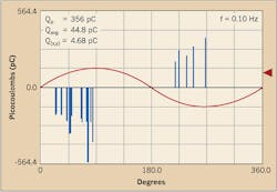
In solid dielectric systems, the PD happens near the peak voltage — both positive and negative. The severity of the PD is measured by measuring the burst interval between the end of a burst and the beginning of the next burst. As the insulation breakdown worsens, the burst interval will shorten due to the breakdown happening at lower voltages. This burst interval will continue to shorten until a critical point is reached. At this point, the discharge is very close to the zero crossing and will fail with a full blown discharge and major failure (Fig. 1).
Where can you find it?
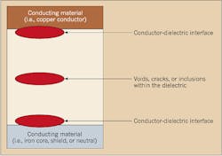
Partial discharge can be found in all types of medium- and high-voltage power equipment — from switchgear, transformers, cables, splices, and terminations to rotating equipment such as motors and generators. PD activity usually begins within voids, cracks, or inclusions within a solid dielectric; at conductor-dielectric interfaces within solid or liquid dielectrics; or in bubbles within liquid dielectrics. Because these activities are limited to only a portion of the insulation, the discharges only partially bridge the distance between electrodes. PD can also occur along the boundary between different insulating materials.
PDs within an organic or polymer insulating material are typically initiated within gas-filled voids within the dielectric (Fig. 2). Because the dielectric constant of the void is considerably less than the surrounding dielectric, the electric field across the void is significantly higher than that across an equivalent distance of dielectric.
Modeling insulation systems
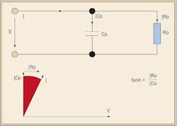
A simplified model of an insulating system can be represented by a capacitance and resistance in parallel (Fig. 3). If the insulation is free from defects, such as water trees, electrical trees, moisture and air pockets, the insulation approaches the properties of a perfect capacitor. It is very similar to a parallel plate capacitor with the two conductive surfaces being the two plates separated by the insulation material. In a perfect capacitor, the voltage and current are phase shifted 90 degrees, and the current through the insulation is capacitive. If there are impurities in the insulation, such as those mentioned above, the resistance of the insulation decreases, resulting in an increase in resistive current through the insulation. The insulating system is no longer a perfect capacitor. The current and voltage will no longer be shifted 90 degrees. The shift will be something less than 90 degrees. The extent to which the phase shift is less than 90 degrees is indicative of the level of insulation contamination. This is the concept employed in the use of Tan Delta testing of insulation systems.
In the Tan Delta test, the tangent of the angle delta is measured. This will indicate the level of resistance in the insulation. By measuring (IR ÷ IC), we can determine the quality of the insulation. In a perfect insulation, the angle would be nearly zero. An increasing angle generally indicates an increase in the resistive current through the insulation, meaning contamination.
Simplified models of voids in insulating systems have been described as consisting of capacitance only. However, when we review the progressive failure mode of these voids, we can also see semiconducting films inside them. These films can also consist of carbonization of organic insulation material within the void due to the arcing damage caused by partial discharge. Thus, the model of the PD void is similar to that of the insulation medium itself and can be represented as a capacitance and resistance in parallel.
Modes of failure
Actual failure modes have indicated a drop in PD intensity shortly prior to complete failure in solid dielectrics. This occurs when the internal arcing had carbonized to the point where the resistive component of the PD void model was low enough to prevent a buildup of voltage across the void. This newly formed low-resistive component would allow higher current to flow and additional heating and resultant insulation degradation. The PD void model, including the resistive component, correlates to the actual failure mode of a PD void — where the resistive component passes more leakage current as the PDs increase with time.
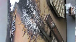
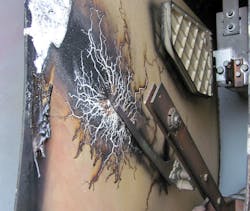
The cumulative effect of PDs within solid dielectrics is the formation of numerous branching partially conducting discharge channels, a process called treeing (Photo 1). Repetitive discharge events cause irreversible mechanical and chemical deterioration of the insulating material. Damage is caused by the energy dissipated by high-energy electrons or ions, ultraviolet light from the discharges, ozone attacking the void walls, and cracking as the chemical breakdown processes liberate gases at high pressure. The chemical transformation of the dielectric also tends to increase the electrical conductivity of the dielectric material surrounding the voids. This increases the electrical stress in the unaffected gap region, accelerating the breakdown process.
Detection techniques
For PD to occur, a sufficient voltage must be applied to the system under test to meet the minimum voltage required to start PD activity. This is known as the PD inception voltage (PDIV). Once the PDIV has been reached, voltage may be lowered, and PD will remain present at the lower voltages until finally they extinguish at what is referred to as the PD extinction voltage (PDEV). The PDEV is therefore less than the PDIV [IEC 60034-27]. If the PDEV voltage level is lower than the system operating voltage (phase to ground), this implies that an overvoltage surge on the insulating system could initiate PD. Even when the system voltage returns to normal, the PD activity may continue.
PD activity that can continue at operating voltage is more likely to result in an insulation failure than PD that extinguishes above normal operating voltage. Provided that PD activity occurs at the operating voltage level, it can be detected and/or measured through online detection methods. Thus, testing for PD activity can be performed either online at operating voltage levels or offline.
Online partial discharge tests are performed at the fixed operating voltage level. To perform online tests, suitable PD coupling methods are required. Over the years, different sensors have been developed to detect PD events. The online coupling methods at switchgear can include:
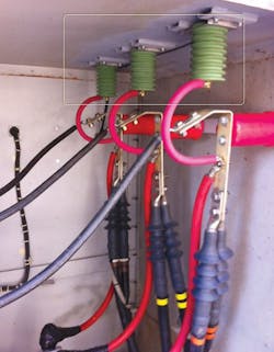
• Capacitive coupling via pre-installed, coupling capacitors (Photo 2)
• Capacitive coupling via already existing taps at current transformer, bushings (capacitive interface for voltage sensing/ voltage detection system).
• Inductive coupling using radio frequency current transducers (RFCT).
• Transient earth voltage sensor (TEV).
• Ultrasonic.
Online PD testing has the obvious advantage in that it does not require disconnecting equipment or taking an outage. The main disadvantage when testing stationary equipment is that the test is only performed at the operating voltage level and cannot be adjusted. Obviously, if the applied voltage is fixed and cannot be changed, the PDIV and PDEV voltages cannot be determined. In comparison to offline testing, where voltages can be adjusted to simulate transients or other overvoltage conditions, a lower percentage of defects can be detected through online methods.
As stated earlier, for PD to occur, a sufficient voltage must be applied to the system under test to meet the minimum voltage required to start PD activity. The online testing approach uses the system voltage of a constant fixed magnitude. In an offline approach, a temporary voltage source will be required. Considerations for an offline voltage source should include:
• The applied voltage should cause PDs in the insulating system under test that have characteristics close, if not identical, to those that occur when the insulating system is in service.
• The temporary voltage source should cause no appreciable damage to the insulating system during the time required to perform the measurements.
• The temporary voltage source should have a variable voltage output so that PDIV and PDEV tests can be performed.
• The size and weight of the equipment required to produce the voltage levels required for testing various assets need to be considered. Is the equipment to be used in a fixed location or a field application?
Voltage sources that are used for commercially available field PD measurement systems will fall into the general categories of power frequency and alternative voltage sources such as very low frequency (VLF). Depending on the type of defect, VLF voltage sources — typically 0.1 Hz for extruded dielectric systems — may require a higher test voltage to generate the same PD level compared with tests performed with power-frequency voltages. For example, the conductivity of the surface of a cavity that has been exposed to PD increases, which allows any charges deposited on the surface by PD to leak away and thus lowers the electric field in the cavity. As more charge can leak away between polarity reversals at VLF than at power frequency, the PDIV at VLF will be larger than that at power frequency. If there has been no previous PD activity to increase the conductivity of the cavity surface, the PDIV at VLF and power frequency will be similar [IEEE Std. 400.3].
Another consideration that needs to be reviewed when comparing online and offline measurements is noise effect on the measurement. In the offline approach, the detection equipment can be calibrated at the time of the test by injecting a known PD pulse level into the specimen under test. This is not possible in the online approach. Further, assets can be isolated during offline testing.
When detecting PD activity using online methods, further analysis will typically be necessary to ensure that the suspect activity was not caused by external noise. It will also be advantageous to locate the source of the PD activity and to quantify and assess the severity of the problem. This can be accomplished by measuring and analyzing activity over time to detect deterioration and to raise an alarm or call-to-action if PD activity reaches a critical level. As an example, if PD activity that is intermittent or possibly influenced by environmental conditions (e.g., changing temperature, humidity, vibration, or electrical noise) is found, temporary installed multi-sensor systems that automatically monitor your plant can be used.
Offline testing of equipment is a good start in establishing inception and extinction levels. This can be done at any time during the life of the asset or as part of the acceptance testing process when the asset is new. Establishing diagnostic test values like dissipation factor at time of acceptance will also provide a good benchmark for moving forward on a predictive maintenance program. This can be viewed as a benchmark survey.
After the equipment has been put into service, periodic online checks can be performed to determine if PD activity is taking place at operating voltage levels. To determine if PD activity is present at operating voltage levels, a simple online general survey can be conducted. The purpose of this survey is to conduct a basic first pass assessment of assets and to check for the presence of PD activity. This is a quick and efficient check that can rule out good equipment in an economical manner. In most cases, nearly 90% of a facility’s equipment will be “good.” The other 10% will need further investigation and will advance to a detailed survey.
If the presence of PD is detected in the general survey, a detailed survey is conducted while the equipment is online. This detailed survey is designed to locate and quantify PD activity in order to produce an asset health report. Once a potential insulation issue has been uncovered, further analysis will be necessary to ensure that the suspect activity was not caused by external noise.
It is also advantageous to locate the source of the PD activity and to quantify and assess the severity of the problem. During this process, multiple sensors and couplers can be deployed for a more detailed survey. Depending on the severity level, PD activity can be measured and analyzed over time to detect deterioration and to raise an alarm or call-to-action if it reaches a critical level. As an example, if PD activity that is intermittent or possibly influenced by environmental conditions (e.g., changing temperature, humidity, vibration, or electrical noise) is found, temporary installed multi-sensor systems that automatically monitor your plant can be used.
Trending diagnostic test data, such as power factor, dissipation factor (Tan Delta), and PDIV/PDEV during scheduled outages, will give further details on the degradation and quality of the insulating systems in critical assets. Implementing an offline and online testing program is the foundation of a true predictive based asset management program, providing the information needed to develop data records of assets, including: current condition and ‘health’ for each asset; time line predictions of likely failure; and the ability to prioritize and schedule maintenance and replacement.
Sandri is a senior technical instructor with Shermco in Dallas. He can be reached at [email protected].
