So you have power circuit breakers at your facility, and they seem to be just fine, sitting there quietly doing their job. What you may not realize is that even though your circuit breakers are apparently working well, behind the scenes these critical devices could be on the brink of failure.
Circuit breakers tend to gather dirt, moisture, and contaminants while in service. Their insulation systems can also weaken due to the heat created by arc interruption, especially if they are not routinely maintained. Circuit breakers used in hostile environments can be exposed to various corrosive contaminants, such as hydrogen sulfide (H2S in oil and gas well equipment) or chlorine (water treatment plants). These aggressive chemicals corrode and damage not only the insulation of the breaker, but also its metal components. This article reviews common DC tests you can perform on circuit breakers to ensure they remain safe and perform in a reliable manner.
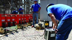
How do you ensure that your customers’ expensive circuit breakers will be ready to respond if there is a fault on their electrical system (Photo 1 above)? The only way to know for sure is by performing the required maintenance, which includes electrical testing of the circuit breakers.
ANSI/NETA MTS-2011, “Standard for Maintenance Testing Specifications for Electrical Power Distribution Equipment and Systems,” provides guidance on what tests and maintenance are required as well as what values you should record when the tests are completed. Three DC electrical tests are among those recommended by the InterNational Electrical Testing Association (NETA):
-
DC overpotential test of the circuit breaker’s insulation systems.
-
Insulation resistance testing of the circuit breaker’s control wiring.
- Contact resistance test to measure the circuit breaker’s current path resistance.
Insulation Systems
The circuit breaker’s insulation system is one important area that requires testing and evaluation. Weak insulation can result in a catastrophic failure, especially during arc interruption. A circuit breaker’s control wiring is also important. One shorted wire within the circuit breaker can prevent it from operating properly, including failure of the spring charging motor or the overcurrent protective device. Circuit breakers that have been in operation for several years can have their factory lubrication dry out, causing it to seize or bind. All of these issues are common in circuit breakers that are in service but have been neglected. Circuit breakers have two primary components to their insulating systems:
-
Arc chutes or vacuum bottles (extinguishers or interrupters).
- Backboard assemblies and/or pole units (primary insulation).
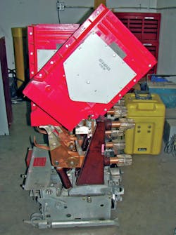
Arc chutes (Photo 2 at right) are one of the most critical elements required to extinguish the arc. Arc chutes must stretch, cool, and contain the arc, even during short circuits. Any defect in the arc chute could cause a restrike — a condition in which the arc re-establishes itself. If a restrike occurs, the circuit breaker cannot clear the fault, and the next device upstream has to operate.
Photo 3 reveals an arc chute damaged by excessive arcing during arc interruption. Photo 4 shows the contact assembly from one phase of a circuit breaker that suffered a restrike. The circuit breaker was so severely damaged that it had to be scrapped.
The backboard assembly (as used on low-voltage breakers and shown in Photo 5) and the pole units (as used on medium-voltage breakers and shown in Photo 6) are used to support the current-carrying components and the arc chutes. The primary insulation of these components tends to degrade with time or suffer from carbon tracking caused by arc interruption. Environmental conditions can also cause deterioration, especially to organic insulations.
Photos 7a and 7b show common types of damage found when performing maintenance on circuit breakers. The destruction shown in Photo 7a will allow moisture to penetrate into the insulation, thus weakening it. The mechanical damage in Photo 7b was found on an inspection.
DC Test Methods
Let’s review the three most common DC tests used to verify the integrity of the insulating components of a breaker.
1) DC overpotential test — The DC overpotential test is one of the standard tests recommended by ANSI/NETA MTS-2011. Placing a high DC voltage across a circuit breaker’s insulation system stresses it so that moisture, dirt, tracking, and weak insulation can be detected. For low-voltage power circuit breakers, you can use a 2,500V megohmmeter for this test. Medium-voltage circuit breakers require the use of a high-potential test set. ANSI/NETA MTS-2011 Table 100.2 gives guidance for overpotential testing of low-voltage circuit breakers and switchgear, and Table 100.19 can be used for medium-voltage circuit breakers and switchgear.
In general, when performing an overpotential test, no specified value is used to evaluate the insulation. If the insulation shows no sign of failure, it is considered serviceable. This is often referred to as a “proof test” or a “Go, No-Go” test, because there are no specific values in ANSI/NETA MTS-2011.
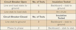
Test connections for the DC overpotential test are given in Table 1 (right), which will provide a test of all possible leakage paths in the circuit breaker. Table 100.19 from ANSI/NETA MTS-2011 provides recommended test voltages for proof testing and field testing medium-voltage power circuit breakers and switchgear (Table 2).
In vacuum circuit breakers, vacuum bottles replace the arc chutes found on air circuit breakers. Vacuum bottles use a partial vacuum to interrupt the arc. In a perfect vacuum, there can be no arc. Because it is physically impossible to achieve a true vacuum, however, some minor arcing within the bottle does occur. The arc drawn is small and quickly interrupted as long as the bottle’s integrity is maintained.
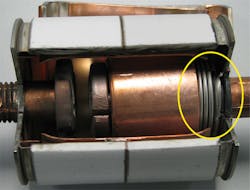
If the flexible metal bellows (shown by the yellow oval in Photo 8 above) develops leakage, air is allowed into the bottle, and the vacuum is relieved. The bellows tend to crack due to the flexing of the metal when the circuit breaker opens and closes repeatedly. The vacuum bottle should contain the failure, but occasionally the hardened casing will rupture. When vacuum bottles fail, they often fail on closing, not opening.
Vacuum circuit breakers can be tested using a DC hipot in the same manner as air-magnetic circuit breakers. There’s good news and bad news here. The good news is a DC hipot can be used to test vacuum bottles. What’s the bad news? Use the wrong DC test set, and the bottle’s toast!
When vacuum breakers first came out, many companies were using the DC hipot method to test their bottles, but it soon became apparent (after the first bottle or two) that something was amiss. Vacuum bottles were failing, even though the recommended test voltage wasn’t being exceeded. That “something” was a voltage spike produced by the half-wave rectifier circuitry used in most DC hipot testers. This spike can be up to 800% of the voltage indicated on the meter.
Due to this issue with DC tests, most manufacturers now recommend using an AC hipot test arrangement for the vacuum bottle integrity test, even though it is not normally used for testing the pole unit (primary) insulation. When performing the vacuum bottle integrity test, the specified voltage (AC or DC) is applied across the vacuum bottle for a specified period of time, and no current is recorded. If it doesn’t fail, it’s good. If it does, it must have been bad. This is known as a “Go, No-Go” test. If the bottle fails during the test, the circuit breaker in the test set will trip.
Hipot test sets that use a full-bridge rectifier do not introduce a spike into the output of the set. This type of circuitry generates a smooth DC output that won’t overstress bottles. Perform this test with the circuit breaker open, and apply the test voltage across the bottles, as shown in Fig. 1, performing the test for each bottle. Be sure to review the instruction manual for the specific vacuum circuit breaker you’re about to test so that you apply the correct voltages. One manufacturer recommends 36kVAC and up to 50kVDC — both for 10 seconds.
Safety warning: Vacuum bottles may emit X radiation if they fail when high voltages are applied. Negligible emissions should result if the manufacturer’s recommended values are used. Higher-than-recommended voltages should never be used. When conducting these tests, stand as far from the circuit breaker as possible, placing the circuit breaker between you and the bottle.
2) Insulation resistance test — An insulation resistance test on low- and medium-voltage circuit breaker’s primary insulation will show gross defects, but to discover tracking, deterioration, and moisture, a DC overpotential test or an AC insulation power factor test is recommended. This is not to say an insulation resistance test should not be performed at all. It can be used for performing a safety check before the breaker is returned to service, and it can also be used to test control wiring,
current transformers, and potential transformers. ANSI/NETA MTS-2011, Table 100.1, provides guidelines for insulation resistance testing of non-inductive electrical equipment, which would include control wiring.
Caution: When performing insulation resistance tests on control wiring on circuit breakers, the high voltage must not be applied to the spring charging motor or solid-state overcurrent devices that may be connected to it. Make sure the device or circuit under test is properly isolated.
All control wiring should have its insulation resistance checked. Wiring that is even slightly out of position can be damaged by wear or cutting on sharp edges. 250V class wiring is tested at 500VDC and should have a minimum insulation resistance of 25 MΩ. 600V class insulation is tested at 1,000V and should have a minimum insulation resistance of 100 MΩ. Measure insulation resistance from the wiring to ground. On a circuit breaker, this would be the frame or chassis.
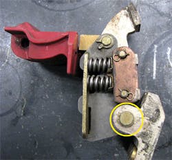
3) Micro-ohmmeter (contact resistance) testing — Manufacturers design contacts and their supporting structures to carry rated load current continuously and, when needed, interrupt the circuit breaker’s rated fault current. For this to happen reliably, the contacts, stabs, and the entire current-carrying structure must have a low resistance. As the resistance of a conductor increases, the amount of I2R losses — losses due to the heat created by current passing through a resistance — increase. Poor contact condition (pitting or misalignment) or aged lubrication in the contact’s pivot (circle) can increase the resistance of the current path. Note that there can be several current-carrying surfaces within the contact structure that require lubrication, depending on the specific design of the contact.
One of the primary reasons to perform the contact resistance test is to determine the condition of the pivot point between the moving and stationary contacts. This pivot, shown in Photo 9 (left), is lubricated when the circuit breakers are manufactured at the factory with a conductive lubricant. As the circuit breaker carries current, this lubricant begins to dry out, becoming gummy and thick. At the same time, the internal resistance of the pivot increases, causing increased I2R (heat) losses, which, in turn, further dries the lubricant. This cycle continues until the lubrication in the pivot fails. With no lubricant, the pivot begins to wear metal-to-metal and elongates the hole, wears the pin, and eventually causes the circuit breaker to seize.
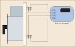
Micro-ohmmeters, which are used to perform contact resistance tests, apply a DC current through the entire closed circuit breaker current path, including the contacts, pivot point, and stab connections of the circuit breaker. The test set read-out displays the contact resistance directly in micro-ohms.
Test connections for the micro-ohmmeter test are shown in Fig. 2 (below). Connect the leads marked C1 and C2 to the outside of the connection points and P1 and P2 to the inside of C1/C2. This prevents reading the resistance of the connection itself. If you’re using spring-loaded probes, the red P1/P2 should be to the outside of the connection.
Although a safety megohmmeter check is not recommended by ANSI/NETA MTS-2011, my company recommends it. Whenever a circuit breaker is removed from its cubicle/cabinet and is left unattended — or after maintenance work has been completed — you should perform a safety check using a 500V megohmmeter. At 500V, no insulation quality will be measured, but lost hardware, misplaced tools, or any other potential short circuit will be. This test is done phase-to-phase with the breaker closed and line-to-load with the breaker open. There should be an “infinite” indication on the meter.
Preventive Maintenance Pays Off
This article reviewed some basic concepts regarding DC testing of circuit breakers. Higher-voltage circuit breakers (2.4kV and higher) will usually rely on insulation power factor tests to determine insulation quality in place of the DC overpotential test, although it is shown as an optional test in ANSI/NETA MTS-2011. The bottom line is you must test circuit breakers in order to find their defects, because the alternative is too risky. A failure in the insulation system could have disastrous results, resulting in a fire, explosion, and injury/fatality.
White is director of training for Shermco Industries in Irving, Texas. He can be reached at [email protected].
