Why perform an arc flash study, label the equipment, and require employees to wear personal protective equipment (PPE)? Many companies want an arc flash study to meet the OSHA requirement to provide employees a safe workplace. Additionally, it just makes good business sense, considering the expense of an accident in lost production time, insurance costs, facility damage, and liability claims.
When it comes to arc flash studies, there are two basic approaches. However, the decision on which one to use is not obvious when you consider the trade-offs. Key documents to help in this decision process include NFPA 70E 2012, “Handbook for Electrical Safety in the Workplace,” and IEEE-1584 2002, “Guide for Performing Arc Flash Hazard Calculations.” Unfortunately, neither one of these completely answers all questions. Before selecting an approach, you must start with a basic understanding of arc flash severity — so let’s start with a quick review.
Arc flash 101
The severity of an arc flash is determined by the magnitude of the incident energy a worker is exposed to during an arc flash. The magnitude of incident energy is determined by three factors:
• Distance from the source.
• Fault current available at the point of work.
• Clearing time of the protective device.
Ensuring accuracy of these factors is critical to determining a valid severity level. Variations of any of these factors can result in significant changes in the available incident energy. For example, it is not unusual for a 2× change in fault current to result in a 10× change in clearing time. A decrease in fault current can increase the clearing time, thus increasing the arc flash threat. That is why it is so common for systems with low fault current to have higher arc flash threats than similar systems with high fault currents.
Table vs. calculation method
NFPA 70E contains two ways to accomplish an arc flash study: one is based on the hazard/risk category (HRC) table; the other requires calculating the incident energy at each piece of equipment. The goal of both approaches is to define the arc flash severity, flash boundary, and required PPE.
NFPA 70E paragraph 130.5 states: “An arc flash hazard analysis shall determine the arc flash boundary, the incident energy at the working distance, and the personal protective equipment that people within the arc flash boundary shall use.” It goes on to say, “The arc flash hazard analysis shall be updated when a major modification or renovation takes place. It shall be reviewed periodically, not to exceed five years, to account for changes in the electrical distribution system that could affect the results of the flash hazard analysis… The arc flash hazard analysis shall take into consideration the design of the overcurrent protection device and its opening time, including its condition of maintenance.”
Exception: The requirements of 130.7(C)(15), and 130.7(C)(16) shall be permitted to be used in lieu of determining the incident energy at the working distance.
The NFPA 70E paragraph requires the calculation of incident energy and then relaxes the requirement in the Exception, allowing the use of the 130.7(C) tables.
The calculation of incident energy, performed in accordance with IEEE-1584, is based on the actual equipment in the system. These calculations also define the distance to the point where the incident energy is below 1.2 cal/cm2 — establishing an arc flash boundary.
The table approach lists an approach boundary for different types of equipment, which frequently does not match the HRC levels listed. To use the boundaries listed, assumptions must be made for the clearing time and short circuit current. Typically, these assumptions basically amount to a best guess because the necessary data is not available to make accurate determinations.
The table approach (see HRC Table Highlights) also provides a group of tables that can be used to determine the PPE requirements based on the voltage, type of equipment, and task being performed — none of which are key factors in determining incident energy. The values contained in these tables were identified by a task group using their collective experience and estimated exposure levels.
The HRC tables list a severity level for each task listed. The use of HRC is intended to only be used with the tables such that it is known that the severity levels are estimates at best.
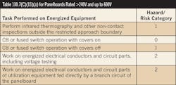
The Table shows a section of the 130.7 Tables for PPE. This section addresses panelboards, which are common in most all electrical systems. Each section of Table 130.7(C)(15)(a) begins with a listing of conditions and the potential arc flash boundary. Let’s take a look at some examples:
Panelboards or other equipment rated at greater than 240V and up to 600V.
• 25kA short circuit current, maximum
• 0.03 fault clearing time, maximum
• 18-inch working distance, minimum
• Potential arc flash boundary with exposed energized conductors: 2 feet, 6 inches
600V motor control center
• 65kA short circuit current, maximum
• 0.03 fault clearing time, maximum
• 18-inch working distance, minimum
• Potential arc flash boundary with exposed energized conductors: 4 feet, 5 inches
600V motor control center
• 42kA short circuit current, maximum
• 0.33 fault clearing time, maximum
• 18-inch working distance, minimum
• Potential arc flash boundary with exposed energized conductors: 13 feet, 9 inches
600V switchgears and switchboards
• 35kA short circuit current, maximum
• 0.5 fault clearing time, maximum
• 18-inch working distance, minimum
• Potential arc flash boundary with exposed energized conductors: 19 feet, 5 inches
Observations regarding the HRC table include:
• The table has no HRC greater than 4 (40 cal/cm2). Actual calculations find that the incident energy is frequently greater than 40 cal/cm2 for switchboards connected directly to electric utility service transformers.
• The table has no 3 or 4 HRCs for switchboards and panelboards, which are common throughout industry.
• What is the basis of changing the clearing times and the setting the short circuit currents for same and different equipment? These are two key parameters in incident energy and are set with no justification.
• There is no instruction on how to determine these critical parameters before using this table.
• The potential arc flash boundaries rarely match the HRC levels.
In many situations, the tables are conservative, requiring more PPE than is typically defined by the incident energy calculations. The switchboard section is a major exception to the conservative listings. Switchboards are commonly connected directly to the electric utility transformer, resulting in a higher fault current. Thus, they may have a more severe hazard level than listed. A mislabeled switchboard that’s actually an HRC 3 or HRC 4 could result in serious injuries to anyone working on this equipment.
The lack of HRCs for incident energy levels greater than 40 cal/cm2 in Table 130.7 creates a serious issue. Paragraph 130.7(A), Informational Note No. 3 states: “When the incident energy exceeds 40 cal/cm2 at the working distance, greater emphasis may be necessary with respect to de-energize before working within the limited approach boundary of the exposed electrical conductors or circuit parts.”
NFPA 70E doesn’t tell users when such a situation may exist. Also note that Informational Notes are explanatory material that isn’t intended to be enforced. This paragraph doesn’t take into account that switchboards connected directly to electric utility service transformers frequently have incident energy levels much greater than 40 cal/cm2 — with boundary levels in excess of 360 inches (30 feet). Equipment with these excessive levels of incident energy needs to be identified and labeled as “Do Not Open While Energized.”
Paragraph 130.7(C)(15) states that if the system has a “greater than the assumed maximum short circuit current capacity or with longer than the assumed maximum fault clearing times,” an incident energy analysis approach is required. Users cannot determine the fault currents or clearing times without doing a detailed analysis. Thus, they generally assume the levels fall within the listed maximum levels. This provides for a significant risk potential in the hazard rating. As previously reviewed, the risk level can be worse if the fault currents are less than the maximum, resulting in the clearing times increasing significantly.
The actual incident energy for a majority of panelboards and MCCs will be less than the level in the HRC table. This results in employees wearing unnecessary PPE (especially if the table is at HRC 3 or 4). The increased PPE can be a source of discomfort and reduced visibility — potentially sufficient to distract the worker from the tasks and increase the possibility of an accident.
The calculation approach provides a more accurate definition of the arc flash severity level by calculating the actual incident energy at the equipment. It also provides an opportunity to determine minor or major changes that could be incorporated to mitigate the existing arc flash hazard. The system model developed as part of the detailed analysis can be updated with additions, removals, or changes made to the power system with minimal effort while maintaining the accuracy of the hazard level.
Woodruff is an electrical safety consultant with AF Services, LLC, Goodyear, Ariz. He can be reached at [email protected].
SIDEBAR: HRC Table Highlights
The severity is determined by:
• Distance from the source
• Fault current available at the point of work
• Clearing time for protective devices
— Not the task being performed
— Not the type of equipment being serviced
The HRC tables in 2012 NFPA 70E provide maximum fault current levels and maximum clearing times.
• Lower fault currents can increase the incident energy as the clearing time increases; thus, maximum levels are not appropriate.
• Clearing times vary by fuse versus breaker, manufacturer, breaker settings, and magnitude of the fault current.
• The tables require the user to make assumptions, which can result in injuries.
The HRC tables assign the flash boundary based on equipment type and assumed fault current.
• In the 2009 version of the standard, the typical flash boundary was 4 feet.
• In the 2012 version, the flash boundaries can be up to 19 feet, 5 inches for an HRC of 1 or 2.
The most critical condition of greater than 40 cal/cm2 is not listed anywhere in the HRC tables.
• This is a critical level that must be addressed; it is the most dangerous arc flash level.
• This is a common level found in many pieces of equipment that provide the first level of protection in the facility.
HRC tables only provide a means of placing labels (that have questionable accuracy) on the equipment.


