When Does Poor Power Quality Cause Electronics Failures?
To many of us, the utility power grid is a vast system of unknowns. Its performance can make unprotected electronic equipment useless. Why? Because grid voltage values, higher or lower than guaranteed nominal values, have an effect on electronic intelligence processing equipment. Incoming grid power “sees” the equipment's DC power supply, which bears the brunt of any AC grid voltage variation.
The impact of voltage sag
We can hardly assume our electronic hardware operates from a distribution network with zero internal impedance, receives a pure undistorted sine wave, and never sees line voltage variations of 55% from nominal. Yet that's exactly what many electronic system manufacturers think when designing their power supplies.
The combination of utility- and locally generated disturbances results in no such modest limits. Most utilities are permitted line voltage reductions (brownouts) to cope with seasonal demands. In addition, large motors accelerating high inertia loads, spot welding, and other loads act to further drop the voltage level delivered to our power supplies.
Computer shutdowns and sag-induced logic errors aren't the only problems. Damage to the DC power supply is a greater danger. Reduced input voltage can cause excessive power supply heat dissipation, resulting in short equipment life. What's behind this overheating? While trying to maintain constant DC output as the line voltage declines, the DC-to-DC converter circuit has to draw from the reservoir capacitor. With line voltage reduced, this capacitor experiences deep discharges between the twice-per-cycle charging periods (see The DC Power Supply: How and Why It Works).
Now, electrolytic capacitors aren't designed for deep discharge — and they're not designed for the resulting large terminal variations. So, the excessive capacitor charge and discharge currents cause internal heat dissipation, which produces dielectric stress. This condition results in reduced mean time between failures (MTBF). In addition, rectifiers and DC-to-DC converter switching transistors draw high-peak currents, which raise their junction temperatures. These temperature excursions take a toll on semiconductor longevity.
The impact of overvoltage, surges, RFI, and harmonics
Short-term voltage surges (10% beyond nominal) aren't usually harmful. However, higher input voltages can overwhelm the voltage regulating ability. The result is damaging voltage levels fed to the electronic circuits.
High input voltage can also puncture a power supply's rectifier and switching transistor junctions, causing MTBF reduction and eventual breakdown. High-voltage transients lasting microseconds can permanently wreck the power supply and its electronic equipment load.
Digital logic circuits that define zeros by voltages in the 0V to 0.5V range and ones by 4.5V to 5V levels are highly susceptible to inductive “kicks” directly impressed on their 5VDC power supply. The power supply's reservoir capacitors don't absorb transient energy, because their wiring inductance (negligible at 60 Hz) introduces isolating impedance at the MHz-equivalent frequencies of fast-rise transients. As a result, transient energy follows the line of least resistance, which is to the power supply's output terminal.
Line-borne noise (RFI and low-voltage transients created by high-current logic circuits) will not likely damage a power supply. However, relatively few power supply designs have careful component shielding and placement. Therefore, line noise can couple (by stray capacitance) to the DC output, where it can disrupt communications and computer circuits. Because this noise may be intermittent and beyond the frequency range of many measuring instruments, you may have trouble diagnosing the source of the malfunction.
Harmonic voltages of the 60-Hz line frequency impressed on the AC power line are also unlikely to damage a power supply. However, higher harmonics of the 60-Hz power supply can fool control circuits. The more numerous zero crossings of higher harmonic frequencies can falsely trigger timing operations the sine wave's zero crossings initiate.
Editor's note: This article was originally featured in the October 1999 issue of EC&M and is updated here to reflect newer switch-mode power supply technologies and performance capabilities.
Sidebar: The DC Power Supply: How and Why It Works
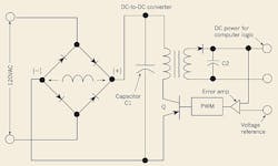
A typical DC power supply (also called a switch-mode power supply or SMPS) is a sophisticated assembly of electronic components. Its basic function is to deliver stabilized low-voltage DC to the digital logic circuit it feeds. Based on a fast-switching DC-to-DC converter, the device converts rectified 60 Hz into the low-voltage DC (typically 5VDC) required by computer logic.
The power supply's pulse-width modulating (PWM) circuit compares the supplied 5VDC output to an accurate 5V reference so that an error-correcting feedback signal develops. This signal adjusts the relative ON and OFF durations of the DC-to-DC converter, holding the output at the required 5V.
An SMPS can bridge a total power outage for periods of up to three complete cycles. However, there's a key requirement for this maximum immunity to happen: The filter capacitor (denoted as “C1” in the Figure) must be fully charged to its design voltage. Basically, this capacitor acts like a short-term battery. During a power outage, this capacitor provides current to the power supply's DC-to-DC converter to keep it running.


