This article is Part 6 of a seven-part series on the effects of power quality disturbances on a five-stage electronic LED driver. Part 1 (April 2018) dealt with long-duration voltage variations. Part 2 (May 2018) dealt with short-duration voltage variations. Part 3 (June 2018) focused on voltage and current transients (including surges). Part 4 (July 2018) dealt with the effects of imbalances (voltage and current) on LED drivers. Part 5 (August 2018) addressed power frequency shifts or changes in the frequency of the voltage delivered to a customer facility. This month, we’ll explore how harmonic waveform distortion may cause damage to electronic LED drivers.
In last month’s article, we covered how power frequency shifts deal with changes in the voltage waveform with respect to frequency (or time). Shortening the period decreased the time between peaks and valleys — making the frequency higher and the opposite for lengthening the period. However, with respect to waveform distortion, you should realize there’s no perfect electrical disturbance. Sags are not just pure sags, and swells are not just pure swells. No 50 Hz or 60 Hz sinewave has a perfect shape.
One of the most famous mathematicians/physicists — Jean-Baptiste Joseph Fourier (1768-1830) discovered the Fourier series. His great discovery states that any mathematical Fourier transform (FT) can be used to decompose a function of time (signal) into the frequencies that make it up. This means that a pure 60-Hz sinewave, which is the fundamental frequency, only contains the frequency 60 Hz. However, when a voltage sinewave becomes “bumpy” or “distorted,” it develops other frequencies that can be decomposed into harmonics of the fundamental frequency.
The use of non-linear electrical elements — inductors and capacitors — on our power system causes shifts in the current with respect to the voltage. These elements (or components) can also cause irregularities in the current and voltage with respect to their wave shapes. These irregularities are sudden changes in any part of the waveform. How do they affect the waveform in real life? They add (or subtract) other sine (or cosine) waveforms (in the case our fundamental is a sinewave) of other frequencies (harmonics) from the total waveform. These harmonics are mathematically described by the Fourier series.
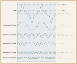
When you add electronic loads to the mix as you have on the grid, the voltage and current waveforms become even more distorted. The old saying, “The voltage belongs to the electric utility, and the current belongs to the customer,” is helpful here. When you place electronic loads on the grid, the power system has a difficult time supplying current at the harmonic frequencies required by the electronic loads. What happens is the voltage supply (e.g., transformers) is limited as to how much energy they can provide at these harmonic frequencies in addition to supplying the fundamental (50 Hz or 60 Hz) frequency at the same time. When the current becomes distorted, the voltage becomes distorted as well because of energy limitations at the harmonic frequencies. Figure 1 illustrates an example of a 50-Hz current sinewave with four of its harmonics (3rd, 5th, 7th and 9th) as well as the total (all five waveforms added together) at the top.
The question now is: “How do these distorted waveforms of current impact our grid and the operation of the electronic loads on it?” We know from studying the power quality effects of harmonic currents on facility power systems that having too much distortion in the current can have dramatic effects on transformers and neutral conductors/bus bars. In transformers, harmonic current flowing through them may cause their windings to overheat due to increased losses associated with the windings having to support harmonic current flow. In neutral conductors, having electronic loads on all three phases of a power distribution panel may cause the current flowing back through the neutral system to experience some unusual additive effect where the RMS current that the neutrals must support is too high, which causes their temperature to increase to values about specific performance limits that can degrade the quality of the conductors or bus bars.
With respect to operating loads, simple loads like incandescent lamps don’t care if the voltage applied to the lamp is distorted. However, when a distorted voltage is applied to an electronic LED driver, the driver may experience some problems.
In most cases, a harmonically distorted voltage will not impact the operation of electronic loads. However, neither building designers, LED driver designers, or installers are watching out for harmonic problems in buildings that could impact driver performance and life. If the harmonic voltage becomes too distorted, the chances of the harmonic content of the voltage affecting the driver increase. Harmonic voltages contain voltages of harmonic frequencies in addition to the fundamental. The fundamental part of the voltage is what drives (or does work) on the driver and causes the driver to energize the LEDs. The harmonic voltages don’t do any useful work on the driver.
However, if the harmonic signature of the voltage waveform contains some harmonic components (amplitude and phase shift) that are unfavorable to the driver, the driver may experience instabilities in the control system of the power supply. The active power factor correction (APFC) part of the circuit in the front end of the driver can react to such harmonic frequencies. If the power supply control points shift, catastrophic damage to power electronic components or controllers can occur.
Unfavorable harmonic voltages can occur in steady-state for periods long enough to cause latent or sudden damage to driver electronics. Designers should be on the lookout for harmonic frequencies that might cause power supply problems.
Straight out-of-the-book industry testing using IEEE or IEC harmonic immunity standards can provide a good start, but doesn’t rely solely on test limits in these standards to determine how your driver might react to real-world harmonically distorted voltages. In fact, it doesn’t take a high total harmonic voltage distortion (Vthd) level to cause problems with electronic loads. VTHD levels as low as 1% to 2 % can cause such problems if the harmonic signature and content of the AC input voltage
waveform is right.
You should not worry too much about the effects of harmonic voltages on the bridge rectifier circuitry. However, be cautious of the peak level in a harmonic laden AC input current waveform. You should be careful to check and be sure the peak current level doesn’t cause any of the inductive elements of the EMI filter to get too close to saturation with respect to the magnetics. If they do, the magnetic component may experience additional overheating and start to weaken its performance with respect to EMI filtering.
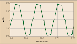
Figure 2 is an example of how much distortion can take place on a voltage waveform. Notice this waveform has severe flat-topping tilted to the right with a discontinuity at the zero crossing. The typical slope of a voltage sinewave is no longer part of the waveform. You should characterize this waveform, determine its harmonic signature, and then apply a permutation of waveforms like this one to determine how well an LED drive might be immunity to typical harmonic voltages present on the AC input.
The most effective harmonic immunity testing for a driver design can be achieved by using an automated test system that has control over the amplitude and phase shifting of various harmonics as applied to the driver under test. There are far too many permutations to try and capture them all in a non-computerized automated test system. Power quality experts can be very helpful in identifying harmonic voltage waveforms and harmonic test levels as well as harmonic test conditions when specifying and designing automated harmonic voltage immunity test systems.
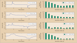
Figure 3 is an example of an LED driver with different types and levels of harmonic filtering on the AC input. This figure shows the current waveform in the time-domain as well as the associated bar chart of the harmonic waveform out to the 19th component. The top figure is an LED driver with no harmonic filtering. Notice the high values of the 3rd and 5th harmonics. The second waveform is harmonic current waveform of the same driver but with a passive filter. Passive filters are tuned to impact the highest harmonic currents — in this case the 3rd and 5th components — but notice that the amplitude of the other components is also reduced.
The third waveform is the same driver but with the application of a “valley fill” filter, which attempts to add some of the current back into the waveform where the “valleys” are located. Notice that it has a dramatic impact on the 3rd, 5th, 7th, and 9th components and very little impact on higher order harmonic currents. The last filter example is an active filter where the filtering is taking place across the entire harmonic current waveform. This is an APFC filter that adds enough current back into the waveform, so the waveform approach is more like that of a sinewave. This filter has less of an impact on the 3rd and 5th harmonics and more of an impact on the 7th and higher order harmonics. Note that the 3rd and 4th filter examples add some voltage transient immunity concerns as more electronic components are added in to the AC front end circuitry of the driver. Pay more attention to the type and degree of surge protection used in the 3rd and 4th driver designs to ensure the immunity to surges is controlled.
You should also note that the power levels associated with an LED driver will impact the performance of a harmonic filter. Typically, higher power levels are associated with higher harmonic current levels, especially in dimmable drivers. Varying power level may have important effects on the harmonic immunity of a driver to real-world harmonic voltages.
Keebler is a power systems and power quality engineer. He can be reached at [email protected].
