Keeping operations running up to speed is at the heart of today’s business world. In a 24/7 environment, there’s no room for error, and giving your customers the most bang for their buck is at the core of many facility management plans. The best way to ensure you supply your customer with the right technology for its needs is to understand the variety and capabilities of available uninterruptible power supply (UPS) systems.
Although UPSs have been around for decades — and the technology behind them is ever evolving — the fundamentals of a UPS system remain constant: to provide near-constant power to critical systems when the main source of power fails by using energy stored in batteries, supercapacitors, or flywheels. Supercapacitors and flywheels are less commonly used, but both have their advantages. Flywheels can be used to reduce space requirements because there is no longer a need for battery storage. Supercapacitors also replace the need for a battery compartment, but are typically used in smaller UPS systems. Batteries are the most common and proven method for data center UPS deployments. This article will focus on the battery application of UPS systems for consistency when comparing the different topologies of the system.
The basics of a UPS system consist of a battery or an energy storage device, a rectifier or power converter, and a switch to transfer power from normal to standby power. Over the years, new technologies for each component of the UPS are implemented to improve efficiency and availability for the system. The arrangements, technologies, and types of components that make up these different elements are what determine the topologies, efficiency, cost, and reliability of the system. Understanding the various topologies of the UPS is key when determining how resilient the system will be.
Types of UPS topologies
There are three key types of UPS system configurations.
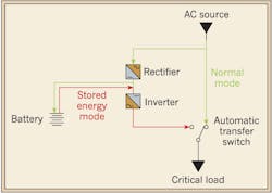
Off-line or passive standby — The most basic topology of a UPS system is the off-line or passive standby UPS. This topology connects the source directly to the load during normal power. In the event of a power failure, the inverter must turn on and transfer power from the battery to the load. The time delay for the invertor to turn on can be long; therefore, this is not recommended for critical systems. It is a simple design consisting of minimal components, making it the least expensive topology (Fig. 1). This topology is common for non-critical applications such as home computing.
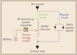
Line-interactive — Line-interactive UPS systems connect the source power to the load through a buffer, which helps to mitigate minor voltage variations and condition the input power to the load. The battery will charge with the inverter operating in reverse during normal operation. During a power failure, the battery will turn on, and the rectifier connected to the load will convert the DC power from the battery into AC power for the load. It is important to note that the power converter is always connected to the output of the UPS (Fig. 2). Always having the inverter on and connected to the battery provides additional filtering and reduced switching transients. This is an efficient design with high availability, but the frequent use of the battery can lead to premature battery failure. A static bypass switch, which will connect the source to the load through a different power path, can be implemented to prevent this premature failure of the battery. This is also considered an eco-mode as it will help reduce the energy consumption of the UPS. The high availability, simple design, and relatively low cost make this system optimal for small businesses.
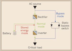
Online or double conversion — The most efficient and robust topology is the online or double conversion UPS system. During normal power, this system will connect the source to the critical load through a double conversion recitifer (Fig. 3). This is essentially a filter circuit that will condition the input signal and provide a more consistent output signal with less voltage irregularities, frequency variations, noise, and other transient behaviors of the input signal. Allowing normal power to flow through the filtering circuit keeps the inverter constantly on, which provides a simple power transfer from normal power to battery. When the power fails, the battery supplies power through the inverter and to the critical load. This topology has a similar option for a static bypass switch to prevent premature battery failure as in the line-interactive system. This system is ideal for large data centers because it has a high availability, can filter the input to provide a conditioned output on the load, and features a resilient design. The cost for this UPS system is the greatest due to the high complexity of the system.
Selection recommendations
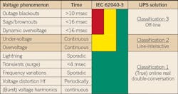
There are many factors to consider when determining the best UPS system for a given facility, such as utility power quality, current-connected load demands, and future load demands. An easy guide to begin the process as to which UPS is right is to look at the IEC standard on UPS classifications. This standard gives three classifications for UPS systems and rates each one based on its ability to handle different voltage phenomenon. Depending on how resilient the facility must be to these fault conditions will determine which type of UPS system is best for the facility. The different voltage phenomena are depicted in Table 1 and range from voltage sags and brownouts to more sensitive voltage phenomena, such as lightning and voltage distortions.
The off-line UPS system will be able to handle the most common of voltage faults and thus is a Classification 3 UPS system. Outage blackouts, which can be caused by power line failure or even routine system maintenance, are the basic reason UPS systems have been deployed. Voltage sags and brownouts can be caused by overloading the system or a utility overload upstream. This is why it’s important to assess the power quality from the utility to determine what the current load demand on the utility is and how often brownouts and voltage sags occur. Most UPS systems have been designed to handle these common voltage phenomena and will satisfy the Class 3 requirement for a UPS system.
A Classification 2 UPS, or the line-interactive type design, will be able to handle more complex voltage phenomenon, such as undervoltage and overvoltage. Since the battery is consistently connected to the load, it can handle instantaneous faults that occur with overvoltage and undervoltage. In contrast, the off-line UPS system (being directly connected to the load) will not be able to handle this condition, and the source will see these conditions.
Finally, the most robust system — a double conversion or online UPS system — will be able to handle lightning, transients and surges, frequency variation, and many other voltage phenomena. This stems from the filtering circuit that is implemented in the topology of this system. This filtering circuit conditions the power before it gets to the critical load, thus protecting the load from upstream faults and voltage distortions. This design has the most protection to the critical load from voltage irregularities and power quality factors. IEC places this system as a Classification 1 UPS system.
Improvements in efficiency
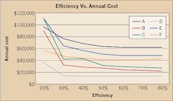
Efficiency is king, and using the latest technology can save your customers a lot of energy. Newer UPS systems can achieve 97% or more efficiency; older generations only achieved 90% to 93% efficiency.
Newer technologies allow for more efficient conversion of power from AC to DC and back. Silicon-controlled rectifier (SCR) technology is very common in older systems but requires a transformer that is inefficient and takes up additional space. Newer systems implement a three-stage insulated gate bipolar transistor (IGBT) technology that allows for a refined, efficient design, which does not require a transformer. This reduces losses through the transformer and size of unit as well as maintenance expenses. Other systems are implementing a six-stage IGBT technology that will further enhance the efficiency and buffer capacity of the UPS system.
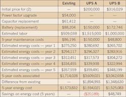
CallisonRTKL performed a study comparing an existing system to new UPS technologies in a live data center. The results showed that by deploying a newer, more efficient UPS, an energy savings of nearly $50,000 can be accrued over a five-year time frame (Table 2).
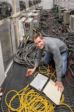
Having a highly efficient UPS that meets the needs of the data center can provide critical power savings and reduced cost throughout the life of the facility (Fig. 4).
Key items to keep in mind
At the end of the day, remember you’re dealing with mechanical devices that can fail. Make sure there’s a backup plan in place, and plan for risk. It’s critical to plan for a redundant system so in the event one system fails another can be quickly implemented to prevent loss of critical data.
Provide a fully maintainable system so that routine maintenance can be performed to extend the life of the UPS and prevent exorbitant replacement costs. This will help prevent unforeseen outages and potential downtime that can be damaging to the data center. The more complex the system, the more components that are inherent in the design. While it will be able to handle more fault conditions, it will require more routine maintenance to ensure proper operation and reduce the risk of failure.
Final thoughts
Determining what is best for the business or facility you’re supporting can depend on a lot of factors. A UPS system has many topologies that vary in resiliency, reliability, availability, and cost. Using tools such as the IEC guidelines can help determine a baseline for your customer’s business needs and provide an idea of the resiliency of the system you recommend and install. It is important to take the total cost of ownership into consideration when recommending a UPS system as a high-efficiency, higher initial cost system could yield higher energy savings in the future. In addition, it’s essential to do a full system cost analysis, system performance, and energy analysis when determining which topology to deploy.
Completing a system study, performance capabilities, and a firm analysis of what is desired will be the most beneficial way to assess the data center and determine which system is best. It is important to understand the power quality from the utility as this could result in needing a more robust system than previously considered. All manufacturers differ in design, efficiency, and reliability, so you must test these systems as well as understand power studies and the performance reliabilities on them to determine which will be most cost effective without losing availability or reliability.
Battish, P.E., is vice president, and Jennings, E.I.T, LEED Green Associate, is an electrical design engineer with CallisonRTKL in Baltimore, Md.
