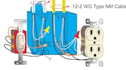
As a representative of the electrical inspection community, I am often asked, “What are some of the most common Code violations you encounter?” While violation of box fill requirements might not be No. 1 on the list, it certainly comes close to the top. Overcrowded boxes are all too common in residential and commercial buildings.
Jamming too many conductors, devices, fittings, etc., into a box — more than what it was designed to hold and listed to contain — is a recipe for disaster. When put to work carrying the loads they were designed to carry, the enclosed conductors produce heat from current flow. These conductors must have ample free space to allow proper dissipation of heat and not cause damage to the surrounding insulation of said conductors. The National Electrical Code (NEC) contains sufficient rules and requirements applying to box fill calculation requirements. Most of these can be found in Art. 314 (outlet, device, pull, and junction boxes; conduit bodies; fittings; and handhole enclosures).
The NEC includes general rules for boxes, such as sizing and support provisions. All boxes (enclosures) must be large enough to provide sufficient free space for all conductors and devices that will be enclosed within them. This will prevent overcrowding and possible physical damage when the devices or splices are installed. Boxes that enclose devices or utilization equipment are to be sized based on the conductors that supply the devices or utilization equipment.
The volume of a box is the total volume in cubic millimeters or cubic inches of the assembled sections. Where used, the space provided by plaster rings, domed covers, and extension rings — all of which are marked with their volume in cubic inches — is included. If the extension ring is made of metal and corresponds to a size listed in NEC Table 314.16(A), then the appropriate volume for that size box is used as the volume of the extension ring. Total volume allowance is the volume of the box plus the volume of any attached plaster rings, extension rings, or domed cover.
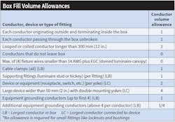
This total volume allowance (i.e., space) determines the number and size of conductors and wiring devices that are permitted to be contained in the box. Conductors, internal clamps, support fittings, barriers, and devices (such as switches and receptacles) take up space within the box. The Code identifies a volume figure for each of these components in the Table above (shown in cubic inches or cubic centimeters).
NEC Table 314.16(B) lists the volume allowance as a function of conductor size. The box must have a volume that equals or exceeds the total volume required for the contained items.
NEC Table 314.16(A) provides box dimension and trade size in inches for standard metal boxes. The minimum cubic millimeter (cubic inch) capacity for each standard size metal box is listed along with the maximum number of conductors (18 AWG through 6 AWG) permitted in the box. As noted in the table, the number of conductors permitted applies only where all conductors are the same size. Where a box contains conductors of different sizes, the required volume of the box must be calculated. A calculation is also required if the box contains devices, clamps, barriers, or support fittings. No volume allowances are required for small fittings, such as locknuts and bushings [see Sec. 314.16(B)].
Metal boxes may be manufactured in sizes other than those listed in Table 314.16(A). This type of box is called a nonstandard box. Nonmetallic boxes made in custom sizes are called nonstandard as well, if their dimensions differ from those shown in Table 314.16(A). All nonstandard boxes must have their cubic millimeter (cubic inch) capacity durably and legibly marked on the inside of the box by the manufacturer.
Requirements for determining the maximum number of conductors permitted in nonstandard or nonmetallic boxes are outlined Sec. 314.16(B). The minimum volume of the box is the total of the individual volumes required for each conductor, device, barrier, or fitting.
A nonmetallic, single-gang device box typically used for new construction does not have internal clamps. The openings on a single-gang nonmetallic box are considered knockouts. Thus, no volume allowance for clamps is required on a single-gang nonmetallic box if the installation complies with Sec. 314.17(C), Exception.
Multiple-gang device nonmetallic boxes and round or octagonal boxes have internal clamps. These clamps may be field-installed or incorporated into the box by the manufacturer. A single volume allowance is made for one or more internal clamps that are present in the box. The volume allowance for clamps that are an integral part of the box construction is included in the marked volume of the box.
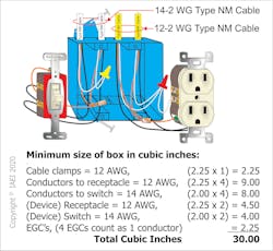
The NEC gives us specific instructions for box fill calculations [Sec. 314.16(B)(1) through (5)] for such things as conductor fill, cable clamps, support fittings, device or equipment fill (e.g., switches, receptacles, etc.), and equipment grounding conductors. An example of the steps involved in this type of calculation is shown in the Figure above.
As this article has demonstrated, several factors must be taken into consideration when determining the maximum number of conductors a box is allowed to contain without creating a Code violation. As stated previously, these enclosed conductors must have ample free air around the conductor and its insulation to allow proper dissipation of self-generated heat. Proper box fill calculations are a vital step in the safe installation of the electrical wiring installed in commercial and residential buildings.
Checking for box fill provisions will eventually become second nature to inspectors and installers if they make it a part of their daily inspection or installation routine. It might seem cumbersome at first, but eventually a box that contains too many conductors will jump off the wall at you if you make box fill calculations an everyday practice.
Lofland is the director of education, codes and standards for IAEI, Richardson, Texas. He represents IAEI as chairman of NFPA’s Code Making Panel (CMP) 7 for the National Electrical Code (NEC), serves on NFPA’s Electrical Section Executive Committee, and is a member of UL’s Electrical Council. He is also the principal author of several IAEI publications, including IAEI’s NEC Analysis of Changes. Prior to his position with the International Office of IAEI, Lofland spent 16 years with the City of Garland (Texas) serving as their chief electrical inspector. He holds a master electrician license from the State of Texas. He can be reached at [email protected].
Inspector Intel articles are provided by the International Association of Electrical Inspectors (IAEI), www.iaei.org, a membership-driven, non-profit association headquartered in Richardson, Texas, that promotes electrical safety throughout the industry by providing education, certification of inspectors, advocacy, partnerships, and expert leadership in electrical codes and standards.


