Stumped by the Code? NEC Requirements When Replacing Nongrounding-type Receptacles
Q. What are the requirements when replacing nongrounding-type receptacles?
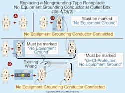
A. If an equipment grounding conductor doesn’t exist in the outlet box, the existing nongrounding-type receptacles can be replaced with [406.4(D)(2)](Fig. 1):
a) A nongrounding-type receptacle.
b) A GFCI-type receptacle marked “No Equipment Ground.”
c) A grounding-type receptacle, if GFCI protected and marked “GFCI Protected” and “No Equipment Ground.”
GFCI protection functions properly on a 2-wire circuit without an equipment grounding conductor because the circuit equipment grounding conductor serves no role in the operation of the GFCI-protection device. See the definition of “Ground Fault Circuit Interrupter” for more information.
If a nongrounding-type receptacle is replaced with an AFCI- or GFCI-type receptacle, they must be located in a readily accessible location.
CAUTION: The permission to replace nongrounding-type receptacles with GFCI-protected grounding-type receptacles doesn’t apply to new receptacle outlets that extend from an existing outlet box that’s not connected to an equipment grounding conductor. Once you add a receptacle outlet (branch-circuit extension), the receptacle must be of the grounding type — and it must have its grounding terminal connected to an equipment grounding conductor of a type recognized in Sec. 250.118, in accordance with Sec. 250.130(C).
Q. What are the rules for the installation of boundary seals for both power and limited-energy wiring?
A. A raceway seal fitting must be installed in each raceway that leaves a Class I, Div. 1 location within 10 ft of the Class I, Div. 1 location on either side of the boundary [501.15(A)(4)]. There must be no fitting, except for a listed explosionproof reducer installed at the raceway seal fitting, between the raceway seal fitting and the point at which the raceway leaves the Class I, Div. 1 location.
Exception No. 1: A raceway boundary seal fitting isn’t required for a raceway that passes completely through the Class I, Div. 1 area unbroken with no fittings installed within 1 ft of either side of the boundary.
Exception No. 2: If the raceway boundary is below grade, the raceway seal can be located above grade, after the raceway emerges from below grade.
A raceway seal fitting must be installed in each raceway leaving a Class I, Div. 2 location. It can be installed on either side of the boundary within 10 ft of the Class I, Div. 2 area [501.15(B)(2)]. Except for listed explosionproof reducers installed at the raceway seal fitting, there must be no union, coupling, box, or fitting between the raceway seal fitting and the point at which the raceway leaves the Div. 2 location.
Raceway boundary seals aren’t required to be explosionproof, but must be identified for the purpose of minimizing the passage of gases permitted under normal operating conditions, and they must be accessible. Note: The raceway boundary seal at unclassified locations is used to minimize the passage of gases or vapors, not to contain explosions in the raceway system.
Exception No. 1: A raceway boundary seal fitting isn’t required for a raceway that passes completely through the Class I, Div. 2 area unbroken with no fittings installed within 1 ft of either side of the boundary.
Exception No. 2: A raceway boundary seal fitting isn’t required for raceways that terminate in an unclassified location where the metal conduit transitions to cable trays, cable bus, ventilated busways, MI cable, or open wiring if:
1) The unclassified location is located outdoors, or the unclassified location is indoors and the conduit system is entirely in one room.
2) The raceways must not terminate at an enclosure containing an ignition source in normal operation.
Exception No. 3: A boundary seal fitting isn’t required for a raceway that passes from an enclosure or a room that’s unclassified, as a result of pressurization, into a Class I, Div. 2 location.
Q. What are the equipotential bonding requirements for permanent pools?
A. The required equipotential bonding is intended to reduce voltage gradients in the area around a permanently installed pool [680.26(A)].
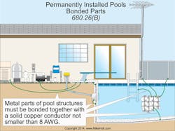
The parts of a permanently installed pool listed in Sec. 680.26(B)(1) through (B)(7) must be bonded together with a solid copper conductor not smaller than 8 AWG with listed pressure connectors, terminal bars, exothermic welding, or other listed means in accordance with Sec. 250.8(A) [680.26(B)] (Fig. 2). Equipotential bonding isn’t required to extend to or be attached to any panelboard, service equipment, or grounding electrode.
As noted in Sec. 680.26(B)(1)(a), unencapsulated structural reinforcing steel in concrete pool shells must be bonded together by steel tie wires.
What about the perimeter surfaces around pools? Equipotential bonding must extend 3 ft horizontally beyond the inside walls of a pool including unpaved, paved, and poured concrete surfaces [680.26(B)(2)]. Note: The NEC doesn’t provide any guidance on the installation requirements for structural reinforcing steel when used as a perimeter equipotential bonding method.
Where structural reinforcing steel isn’t available (or is encapsulated in a nonconductive compound such as epoxy), equipotential bonding meeting all of the following requirements must be installed [680.26(B)(2)(b)]:
1) The bonding conductor must be 8 AWG bare solid copper.
2) The bonding conductor must follow the contour of the perimeter surface.
3) Listed splicing devices must be used.
4) The required conductor must be located between 18 in. and 24 in. from the inside walls of the pool.
5) The bonding conductor must be secured in or under the deck or unpaved surface within 4 in. to 6 in. below the subgrade.
Metallic parts of the pool structure must be bonded to the equipotential grid [680.26(B)(3)].
Metal forming shells and mounting brackets for no-niche luminaires and speakers must be bonded to the equipotential grid [680.26(B)(4)].
Metal fittings 4 in. and larger located within or attached to the pool structure, such as ladders and handrails must be bonded to the equipotential grid [680.26(B)(5)].
Metal parts of electrical equipment associated with the pool water circulating system, such as water heaters, pump motors, and metal parts of pool covers must be bonded to the equipotential grid [680.26(B)(6)].
Exception: Metal parts of listed double-insulated equipment aren’t required to be bonded. If a double-insulated water-pump motor is installed, a solid 8 AWG copper bonding conductor must be provided for a replacement motor [680.26(B)(6)(a)].
All fixed metal parts must be bonded to the equipotential grid, including but not limited to, metal-sheathed cables and raceways, metal piping, metal awnings, metal fences, and metal door and window frames [680.26(B)(7)].
Exception No. 1: If separated from the pool structure by a permanent barrier that prevents contact by a person.
Exception No. 2: If located more than 5 ft horizontally from the inside walls of the pool structure.
Exception No. 3: If located more than 12 ft measured vertically above the maximum water level.
If the pool water doesn’t have an electrical connection to one of the bonded parts described in Sec. 680.26(B), an approved corrosion-resistant conductive surface that’s at least 9 sq in. must be in contact with the water. The corrosion-resistance conductive surface must be bonded in accordance with Sec. 680.26(B), and be located in an area where it won’t be dislodged or damaged during normal pool usage [680.26(C)].
Holt is the owner of Mike Holt Enterprises, Inc. in Leesburg, Fla. He can be reached at www.mikeholt.com.


