As we saw in Part 1, the correct sizing of conductors is more complicated than it appears. One of the reasons is the way temperature affects the resistance of a conductor. Higher temperatures mean less current-carrying capacity for a given size conductor. A conductor may have sufficient ampacity at one temperature, but at a higher temperature it just can’t take the heat.
We use ampacity tables to select the correct ampacity, but the ampacity tables are based on 86°F. What if your application is at a different temperature?
First, determine the maximum temperature of the location in which the conductors will run. This is the temperature at which your conductors will need to carry current at some point, not the average temperature over which they must carry current. If the conductors lack sufficient capacity for the actual operating conditions, results may be catastrophic.
Next, correct for the difference between your application’s temperature and the 86°F temperature basis of the tables. If more than three current-carrying conductors are bundled, you must make further adjustment.
Now you’re ready to select the minimum conductor size from the table. But there’s a catch: you can’t use a column whose temperature exceeds the temperature rating of any device in a given run.
You’ll normally use the 60°C column even if you’re running 90°C conductors. You can use the 90°C column, but only if:
• Your terminal devices are all are rated at 90°C, or
• Your run doesn’t contain terminals. Not all runs do; see Informative Annex D, Example D3(A).
This requirement [Sec. 110.14(C)] sometimes results in calculation mistakes. But it also prevents potentially lethal installation mistakes. How so? Termination devices (e.g., lugs) are sized to fit specific conductor sizes, so this requirement forces using adequately sized termination devices. It also prevents using a “derated” termination device that is actually too large for the conductor. You derate the conductor — not the termination device or other terminal device.
Adding more complexity is the fact that you don’t size all conductors the same way. It also matters whether the conductors are in a branch circuit or a feeder.
Branch circuits
The ampacity of branch circuit conductors must be at least the maximum load to be served [Sec. 210.19(A)(1)]. So size the conductors to carry the larger of:
1. 125% of the continuous loads, plus 100% of the noncontinuous loads, based on the terminal temperature rating ampacities as listed in Table 310.15(B)(16); or
2. The load after the application of correction or adjustment factors.
Let’s run through an example problem now to clarify the steps required to properly size a conductor.
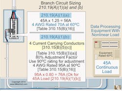
Question: What’s the minimum size branch circuit conductor (THHN) for a 45A continuous nonlinear load that requires three ungrounded conductors and a neutral (four current-carrying conductors)? (See Fig. 1.)
Here are the key steps in solving this problem:
Because the load is 45A continuous, the conductor must have an ampacity of at least 56A (45A ´ 1.25) [Sec. 210.19(A)(1)(a)].
Table 310.15(B)(16), 75°C column shows a 4 AWG conductor is suitable, because it has an ampere rating of 70A at 60°C before applying any conductor ampacity adjustment and/or correction.
Because the neutral is a current-carrying conductor per Sec. 310.15(B)(5)(c), you have four current-carrying conductors. Therefore, you must apply a Table 310.15(B)(3) adjustment factor of 80% [Sec. 210.19(A)(1)(b)].
4 THHN is 95A at 90°C [Table 310.15(B)(16)].
Adjustment factor for four current-carrying conductors is 0.80 [Table 310.15(B)(3)(a)].
Therefore, the Corrected Ampacity = 95A × 0.80 = 76A. This is adequate for the 45A load.
Feeders
In one respect, sizing feeder conductors is notably different from sizing branch circuit conductors. Here’s how you do it:
First, size the overcurrent protection device (OCPD). Feeder OCPDs must have a rating of at least 125% of the continuous loads, plus 100% of the noncontinuous loads.
Next, size the conductor. As with branch circuits, use the larger of two sizes [Sec. 215.2(A)(1)]:
1. 125% of the continuous loads, plus 100% of the noncontinuous loads, based on the terminal temperature rating ampacities as listed in Table 310.15(B)(16); or
2. The load after the application of correction or adjustment factors.
The second step is the same, but not the first step. The difference is that you size branch circuit conductors to serve the branch circuit load and feeder conductors to serve the feeder OCPD.
This difference makes sense when you think about the purpose of feeder circuit conductors (carry power from the source to the final OCPD) versus the purpose of branch circuit conductors (carry power from the final OCPD to the outlets).
This difference in purpose has so many effects on design that the NEC provides separate Articles for branch circuits [210] and feeders [215].
Taps
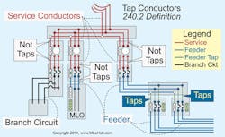
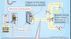
Feeders bring another twist to conductor sizing: feeder tap rules. A tap is a conductor (other than a service conductor) with overcurrent protection rated higher than normally allowed in Sec. 240.2 (Fig. 2).
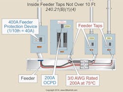
You can run feeder taps without overcurrent protection (at the tap location), up to 10 ft (Fig. 3). But only if the ampacity of the tap conductor is at least the:
1. Calculated load per Art. 220, and
2. Rating of the device or OCPD supplied by the tap conductors.
Also, the tap conductors must:
1. Not extend beyond the equipment they supply.
2. Be in a raceway, if they leave the enclosure.
3. Have an ampacity at least one-tenth of the rating of the OCPD that protects the feeder.
Again, let’s run through an example problem to drive home the points we just presented.
Question: Using the 10-ft tap rule, what’s the minimum size conductor you need to supply a 200A OCPD, if the tap is from feeder conductors protected by a 400A OCPD?
The ampacity of the tap conductors must be at least the rating of:
• The 200A OCPD they terminate into, and
• One-tenth the rating of the OCPD protecting the feeder conductors.
A 3/0 AWG conductor:
• Is rated 200A at 75°C, and
• Has an ampacity of at least 40A (one-tenth the rating of the 400A feeder OCPD (400A ÷ 10) [Table 310.15(B)(16)].
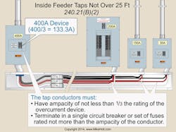
What if you need a longer tap? If you don’t need to go more than 25 ft, you’re in luck [Sec. 240.21(B)(2)]. However, you must satisfy three requirements to get that additional 15 ft (Fig. 4):
1. The ampacity of the tap conductors must be at least one-third the rating of the OCPD that protects the feeder.
2. The tap conductors must terminate in a single circuit breaker (or set of fuses) rated no more than the tap conductor ampacity per Sec. 310.15 [Table 310.15(B)(16)].
3. The tap conductors must be protected from physical damage by being enclosed in a manner approved by the authority having jurisdiction (e.g., within a raceway).
Here’s one last example problem to review.
Question: Using the 25-ft tap rule, what’s the minimum size conductor to supply a 200A OCPD, if the tap is from feeder conductors protected by a 400A circuit?
The tap conductors must have an ampacity of at least the 200A rating of the OCPD they terminate into and at least one-third the rating of the OCPD protecting the feeder conductors. A 3/0 AWG conductor is rated 200A at 75°C and has an ampacity of at least 133A (one-third the rating of the 400A feeder OCPD (400A ÷ 3) [Table 310.15(B)(16)].
The great outdoors
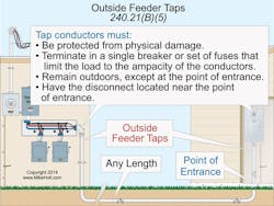
And just when you thought the feeder conductor fun was over, we have one more twist to talk about. The good news is there’s no limit on how long an outside feeder-tap can be without overcurrent protection at the point it receives its supply [240.21(B)(5)] (Fig. 5). But only if:
1. The tap conductors are suitably protected from physical damage in a raceway or manner approved by the authority having jurisdiction (AHJ).
2. The tap conductors terminate at a single circuit breaker (or single set of fuses) that limits the load to the ampacity of the conductors.
3. The OCPD for the tap conductors is an integral part of the disconnecting means, or is located immediately adjacent to it.
4. The disconnecting means is at a readily accessible location (either outside the building), or nearest the point of entry of the conductors.
Branch vs. feeder
It can be hard to remember whether you size the OCPD first for branch circuits or for feeders. The rules differ because each type of circuit serves a different purpose, but that fact alone may not help you keep things straight.
Perhaps another way of looking at it will help. The conductors of a branch circuit must be big enough to supply the branch circuit loads. But the conductors of a feeder circuit must be big enough to serve the feeder OCPD.
Holt is the owner of Mike Holt Enterprises, Inc. in Leesburg, Fla. He can be reached at www.mikeholt.com.
