All references are based on the 2011 edition of the NEC.
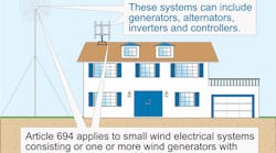
When used for specific loads, small wind electric systems (SWESs) are often the sole power source. When used for general power, however, they usually supplement another power source. Each individual wind turbine in this classification range must be power rated 100kW or less [694.1], as shown in Fig. 1. Keep in mind that while Art. 694 does not limit the number of wind turbines that can be installed at one location, a single wind turbine is the typical installation covered by the installation rules of this Article.
Fig. 1. The NEC devotes a little more than five pages to outline the requirements for installation of small wind electric systems.
An obvious key factor for an SWES is wind availability. With a sufficiently large enough battery system (covered by Art. 480), it’s possible to overcome limitations on this front — but only in areas with short-term, low wind conditions.
Although SWESs generally aren’t a good option for the sole power source to a building, they quite often are an excellent option for the sole source to specific loads. For example, a farm might use an SWES to provide power for well water pumps. The pumps fill a storage tank while there’s sufficient power to run them. The tank has enough capacity to ride out the low wind period. Similarly, an industrial facility might use an SWES to run sump pumps. Because rain and wind arrive together, this is an ideal application. Another suitable application is powering a pond aerator. Because the aerator doesn’t need to run constantly, if the wind dies down for a day or so, the outage isn’t a problem. The SWES also eliminates the need to run power from the main building to the pond.
Today’s typical SWES installation uses engineered kits that come in designated kW output packages. For example, you can buy a 10kW wind turbine kit. The mechanical engineering that goes into these kits removes much of the complexity from assembly and installation while boosting power efficiency.
The basic electrical system of an SWES consists of three components: a generator (or alternator), inverter, and controller [694.1]. The system can have an AC or DC output. It can have electrical storage (e.g., batteries) or not. The turbine assembly might be mounted on a mast, tower, flange, or roof. If it’s mounted on a guyed tower, then the installation has another layer of complexity added to it. So the total installation effort can be considerable and involve engineering challenges across several disciplines — even if you’re using a predesigned kit.
Sole power source systems
If you’re using the SWES as the sole power source (stand-alone power source), the premises wiring must be adequate to meet the NEC requirements for a similar installation connected to a service [694.18].
The NEC doesn’t require energy storage or backup for an SWES, but your operating requirements might. The AC inverter of a stand-alone SWES can provide power to the structure disconnect, but only if the current levels are less than the calculated load to that disconnect. Use an inverter rated large enough to supply the largest single utilization equipment connected to the system. The inverter output rating can’t be less than the load of the largest single utilization equipment connected to the system. You can’t use the calculated general lighting loads as a single load [694.18(A)].
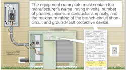
Size the circuit conductors between the inverter output and the structure disconnect based on the inverter output rating. Provide overcurrent protection per Art. 240, and locate overcurrent protection devices (OCPDs) at the output of the inverter [694.18(B)], as shown in Fig. 2.
Fig. 2. The overcurrent protection requirements for stand-alone wind electric systems can be found in Sec. 694.18 of the NEC.
You can supply 120V circuits from the inverter output to single-phase, 3-wire, 120/240V service equipment, but only if there are no 240V outlets or multiwire circuits [694.18(C)]. This equipment must be marked with the following words or equivalent:
WARNING
SINGLE 120V SUPPLY
DO NOT CONNECT
MULTIWIRE BRANCH CIRCUITS!
In addition, a plaque or directory must be installed on the exterior of a building or structure at a readily visible location, indicating the location of the stand-alone system disconnect. The plaque also must state that the structure contains a stand-alone electrical power system [694.54(A)].
If the SWES has energy storage (e.g., batteries), mark the storage system with the maximum operating voltage, any equalization voltage, and the polarity of the grounded circuit conductor [694.52].
Supplementing other power sources
While powering small loads is one way that SWESs are effective, they are also useful as a means of supplementing the main source — which isn’t always the electric utility grid. In a remote location, for example, the main source might be a gas turbine.
When an SWES supplements the electric utility power source, we say that the system is interactive. It will have an inverter to change the power coming in from the wind turbine to power being supplied by the electric utility power source. Ideally, it will also have a bypass switch, but the NEC does not require that. Nor does it require you to provide an operational tutorial to homeowners when you’ve installed an interactive residential system. However, doing so is a good business practice for a variety of reasons, including potential liability.
You need to provide some marking and signage for interactive systems above what’s required for non-interactive systems. Mark all points of interconnection (with other sources) at an accessible location at the disconnecting means [694.50]. The marking must show the rated AC output current and the nominal AC voltage.
Install a permanent plaque or directory to indicate the location of the service disconnecting means and of the SWES disconnecting means [694.54(B)]. It is this plaque that will inform firefighters how to de-energize the premises. The NEC doesn’t specify the location of this plaque, but the exterior of the building or structure at a readily visible location should meet the intent of this requirement.
Connecting interactive systems
Use only inverters listed and identified as interactive [694.60]. If you’re connecting this SWES to an electric utility source, comply with Art. 705 [694.62]. If connecting to a gas turbine source or other non-utility source, this isn’t necessary. However, regardless of what the other source is, all points of connection must comply with 705.12.
An SWES connected to dedicated branch or feeder circuits can exceed normal voltage operating ranges on these circuits — but only if the voltage at any other distribution equipment supplying loads remains within normal ranges [694.66].
Overcurrent protection
Protect turbine output circuits, inverter output circuits, and storage battery conductors and equipment with OCPDs sized per Art. 240. As these are continuous loads, size the OCPDs to carry at least 125% of the calculated maximum circuit current [694.12].
What’s the calculated maximum circuit current? Actually, there are three:
1) Turbine output. Circuit current of the wind turbine operating at maximum output power [694.12(A)(1)].
2) Inverter output. Continuous output rating of the inverter [694.12(A)(2)].
3) Inverter input (stand alone). Stand-alone continuous inverter input current rating of the inverter producing rated power at the lowest input voltage [694.12(A)(3)].
Disconnects
An SWES that uses the turbine output circuit for regulating turbine speed doesn’t require a means of disconnecting the turbine output circuit from the premises wiring [694.20 Ex.]. For all other types of SWESs, you must supply a readily accessible means of disconnecting the SWES current-carrying conductors from all other conductors in the structure [694.20].
Don’t install a switch, breaker, or other device in a grounded conductor if its operation leaves the grounded conductor energized.
Permanently mark each SWES disconnect to identify it as such. Install a plaque per 705.10 [694.24(C)(2)].
Wiring methods
You can use any applicable Chapter 3 wiring method. You can also use any wiring systems and fittings specifically intended for use on an SWES. If an accessible circuit operates at more than 30V, run it in raceway [694.30(A)].
Flexible cords used to connect the moving parts of the SWES must comply with Art. 400. They must be:
• Suitable for extra-hard usage
• Listed for outdoor use
• Water-resistant.
If exposed to sunlight, they must also be sunlight-resistant [694.30(B)].
If installed indoors, turbine output circuits that are DC must be enclosed in metal raceway and enclosures [694.30(C)].
Grounding
Except for the tower and guy lines, bond all non-current-carrying metal parts and equipment to the equipment grounding conductor [694.40(A)]. This puts the SWES in compliance with Art. 250, Part V and prevents dangerous differences of potential.
Fig. 3. As is the case with all electrical equipment installations, bonding and grounding requirements are key to a safe installation.
For lightning protection purposes, ground the tower to at least one auxiliary electrode. Auxiliary electrode(s) can be installed in accordance with 250.54 (Fig. 3). Concrete-encased electrodes installed in accordance with 250.52(A)(3) that are part of the tower foundation can be used as the auxiliary electrode [694.40(C)].
Run an equipment grounding conductor between the turbine (turbine/tower assembly) and the premises grounding system, per 250.110, [694.40(C)(2)]. Failure to do this could result in a large difference of potential between premises wiring and the turbine.
Additional considerations
With standard kits, the design issues of the turbine/generator system itself are already solved for you. However, a successful installation depends on many other factors, including intended use, turbine siting, controls location, and user sophistication level.
You may also have to consider minimum, maximum, mean, and average wind conditions. You need some training and experience in dealing with those issues if you are responsible for the whole project.
While it doesn’t address these other issues, the NEC does address the electrical safety requirements of these installations. For the most part, the electrical work is like that of any normal installation. For example, size your circuits the same way you’d size any continuous load circuits. Article 694 adds signage and marking requirements among a few other SWES-specific requirements. If your company plans to do many SWES installations, develop a checklist of these additional requirements and use that in the field.
Holt is the owner of Mike Holt Enterprises, Inc. in Leesburg, Fla. He can be reached at www.mikeholt.com.


