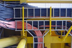
Cable trays solve many design and installation problems, save money, and produce a neat, durable installation. For industrial establishments, strongly consider using cable trays whenever it is permitted for applications that include many conductors. Cable trays are permitted for other kinds of establishments, too. But you cannot use them in hoistways or where subject to severe physical damage [Sec. 392.12].
The iconic structure of a cable tray is the ladder system. But it’s not the only structure. Other structures include ventilated trough, ventilated channel, and solid bottom.
A cable tray system consists of:
- A unit or assembly of units or sections.
- The associated fittings.
Assembled together, these form a structural system that can securely fasten or support cables and raceways [Sec. 392.2]. You can use cable trays as a support system for wiring methods containing:
- Service conductors.
- Feeders.
- Branch circuits.
- Communications circuits.
- Control circuits.
- Signaling circuits.
Some caveats on installation:
- You must install any cable tray as a complete system [Sec. 392.18(A)].
- You must complete each run of cable tray before installing the conductors [Sec. 392.18(B)].
- Cable trays shall be exposed and accessible [392.18(E)], except as permitted by Sec. 392.18(D).
- You can run cable trays transversely through partitions and walls or vertically through platforms and floors if the installations, complete with installed cables, conform to Sec. 300.21 [Sec. 392.18(D)]; that is, those installations are made such that the possible spread of fire or products of combustion is not substantially increased.
- Follow the applicable portions of Sec. 392.22 to determine how many conductors you can install.
Due to its big cross-section, a cable tray makes an equipment grounding conductor (EGC) [Sec. 392.60]. But if you use it for that purpose, ensure the system is electrically continuous. You must also ensure the cable tray will be serviced and maintained by qualified personnel to preserve mechanical integrity and all-important electrical continuity.
For a cable tray on the load side of the power source, don’t make any connections to ground (earth); see the definition of ground in Art. 100. What you should have on the load side is a bonding system, where individual items connect to the EGC that ultimately runs back to the grounding connection at the source. If you ground on the load side, you fail to eliminate dangerous differences of potential but might very well succeed in creating dangerous ground loops.
About the Author

Mark Lamendola
Mark is an expert in maintenance management, having racked up an impressive track record during his time working in the field. He also has extensive knowledge of, and practical expertise with, the National Electrical Code (NEC). Through his consulting business, he provides articles and training materials on electrical topics, specializing in making difficult subjects easy to understand and focusing on the practical aspects of electrical work.
Prior to starting his own business, Mark served as the Technical Editor on EC&M for six years, worked three years in nuclear maintenance, six years as a contract project engineer/project manager, three years as a systems engineer, and three years in plant maintenance management.
Mark earned an AAS degree from Rock Valley College, a BSEET from Columbia Pacific University, and an MBA from Lake Erie College. He’s also completed several related certifications over the years and even was formerly licensed as a Master Electrician. He is a Senior Member of the IEEE and past Chairman of the Kansas City Chapters of both the IEEE and the IEEE Computer Society. Mark also served as the program director for, a board member of, and webmaster of, the Midwest Chapter of the 7x24 Exchange. He has also held memberships with the following organizations: NETA, NFPA, International Association of Webmasters, and Institute of Certified Professional Managers.
