Inevitably, industrial facilities are going to have 460VAC, 3-phase motor loads. And, of course, since voltage drop is considered mainly a performance issue, maximum voltage drop rules on a circuit aren’t dictated by the National Electrical Code (NEC) as a requirement.
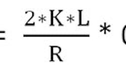
You can discuss this issue with a dozen different design engineers or electricians, and you’ll get a dozen or more opinions on how to best approach calculating voltage drop. And, you’ll see at least a dozen different formulas. But, at the heart of all voltage drop calculations is Ohm’s Law (i.e., V = I x R).
The example below illustrates a simplified method to calculate voltage drop in a branch circuit. Let’s say we have a Design B, 100-hp, 460V, 3-phase, 60Hz squirrel cage motor on a branch circuit. The wire type is stranded copper, Type XHHW-2 [use parameters of Table 310.15(B)(16)]. The length of the circuit is 600 ft, one way. We want to maintain a 3% voltage drop (max.) while the motor is running. We also want to maintain a 10% volt drop (max.) on locked-rotor current, when the motor is starting. Terminals are rated at 75°C on the breaker and at the motor. There are three steps to solving this problem.
Step No. 1: Find the minimum wire size as per Code.
• Find full-load current in Table 430.250 [100 HP = 124A]
• Multiply by 1.25 [124A X 1.25 = 155A rated conductor (min.)]
• Minimum wire size by this calculation alone would be 2/0 AWG copper.
Now we need to make sure the motor will start and also run properly on this size wire. To do this, we need to look at both the running full-load amperage and the starting (locked rotor) amperage and compare the required wire sizes for these conditions with the minimum wire size identified above. Then, we’ll take the largest of the three solutions.
There are many different ways to calculate voltage drop. This is one of the easier methods. Granted, it’s not highly scientific, but the results are typically close enough for everyday calculations.
Here’s a list of the individual components we’ll use in our formulas and calculations.
EVD = voltage drop (in this example, EVD = 460V x 3% = 13.8V)
R = resistance (in this example, resistance = impedance)
I = amperage
CM = circular mil of wire
K = constant of copper (K=12.8 in this example)
L = length of circuit (one way)
0.866 = 1.732 (square root of 3 divided by 2)
Step #2: Solve for motor running (full-load current) minimum wire size with a 3% voltage drop.
R = V ÷ I = 13.8V ÷ 124A = 0.1113 ohms
119,513 CM = 2/0 AWG, as per NEC Table 8, Chapter 9
It would only require a 1/0 copper wire to maintain a 3% voltage drop on this circuit. However, our minimum wire size so far is 2/0 per NEC requirements. So lastly, we need to make sure the motor will start.
Step #3: Solve for voltage drop with locked-rotor (starting current) with a maximum 10% drop (NEMA MG-1).
Locked Rotor Amps for 100 HP, Design B motor = 725A [NEC Table 430.251(B)]
460V x 10% volt drop (max) = 46V
R = 46V ÷ 725A = 0.06345 ohms
209,642 CM = 4/0 AWG
The largest wire size of the three is 4/0 AWG. Therefore, we require a 4/0 AWG in this case instead of the 2/0 AWG required by the NEC.
Keep in mind that there are many variables that can affect the outcome of these calculations. Among them:
1) Nominal voltage used in this example is 460V. Actual system voltage may be higher or lower which would affect the calculations, and thus alter the outcome for the wire size (i.e., either larger or smaller).
2) Actual impedance may need to be accounted for. For three, single conductors in conduit at 75°C, (167°F), NEC Chapter 9, Table 9 can be used. Of course, rarely will we encounter such a high temperature, which is what this table is based on. A lower temperature will change the constant of copper, and thus could reduce the wire size.
Note: While the example above shows a relatively simple way to calculate voltage drop, only qualified individuals should design electrical circuits and all applicable parameters should be taken into account when doing so.
© 2016 Fluor Corporation. All Rights Reserved.


