Article 427: Fixed Electric Heating Equipment for Pipelines and Vessels
Among its other uses, this equipment keeps process plants running and gas flowing through pipelines in cold weather. But installation errors can defeat the purpose of installing this equipment. It’s not just that a pipeline or vessel can freeze and the material inside it be unavailable for use. It can freeze and rupture, causing extensive environmental damage or worse.
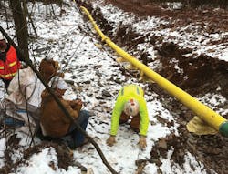
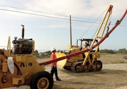
Freeze protection (Photo 1) is what most people think of first, but many heat-tracing systems are not for freeze protection. The applications are numerous. For example, the system’s job may be to maintain fluid temperature to lower the viscosity for better flow (Photo 2).
To prevent failure:
- Use only equipment that’s identified as being suitable for the chemical, thermal, and physical environment [427.10].
- Install the equipment per the manufacturer’s drawings and instructions, and follow applicable industry standards [427.10].
- Carefully determine what physical hazards might result in physical damage to the equipment, and provide the necessary protection [427.11].
Also:
- For external surfaces of heating equipment operating above 140°F, protect personnel from contact by installing physical guards, isolating the equipment, or thermally insulating the equipment [427.12].
- Every 20 ft or less along any electrically heated pipeline or vessel, post the appropriate caution signs or markings to indicate the presence of this equipment [427.13]. The NEC requires this if the equipment needs periodic servicing, but something similar is wise even when there’s no periodic servicing.
Disconnects
You must provide a disconnect that can be locked open and that simultaneously opens all of the ungrounded conductors [427.55(A)]. At this voltage level, the neutral is the grounded conductor. So you can typically wire these with a switch that “opens the hot” (the other conductor) to break the circuit. But you may not need that switch. If the branch circuit switch or breaker is readily accessible to the equipment user, it can serve as the disconnect.
Carefully review the drawings to verify the disconnect will remove all power in the circuit and thus provide certain (no chance of backfeed) isolation of the equipment. Using the supply breaker as the disconnect will automatically accomplish this.
If the equipment is cord- and plug-connected and rated 20A (or less) and 150V (or less) to ground, you can use the plug as the disconnect if it’s factory-installed [427.55(B)].
Controls
The NEC recognizes four types of controls for these systems:
- Temperature control with “OFF” position [427.56(A)]. If these interrupt the line current, they must open all ungrounded conductors when in the “OFF” position. They can be used as the disconnect only if lockable in the open position.
- Temperature control without “OFF” position [427.56(B)]. These don’t have to open all ungrounded conductors, and can’t be used as the disconnect.
- Remote temperature controller [427.56(C)]. These don’t have to meet the requirements for the previous two types of controls, and can’t be used as the disconnect.
- Combined switching devices [427.56(D)]. Temperature-actuated devices combined with manual switches that serve as both the controller and the disconnect must open all ungrounded conductors when in the “OFF” position, be lockable in the open position, and prevent automatic energization of the circuit.
Overcurrent protection
It’s important to note these heaters are continuous loads [427.4]. That means you multiply them by 125% for load calculation purposes.
You must supply the equipment with a branch circuit as specified in 210.3 and 210.23 [427.57]. 210.3 basically says the rating of the OCPD is the rating of the branch circuit. 210.23 is a bit more complicated. It begins with an obvious requirement — namely that you can’t have more load on that circuit than what the OCPD is rated for.
One requirement is that utilization equipment fastened in place not exceed 80% of the OPCD rating [210.23(A)(1)]. If you also have lighting units and/or cord- and plug-connected equipment on that circuit, the fixed equipment can’t exceed 50% of the OCPD rating. If your heating equipment load exceeds 50A, you cannot have any lights on the circuit [210.23(D)].
There may be a cost-driven reason to mix other loads in with your heating loads but, if possible, you want to avoid this. For one thing, suppose the lights are there for maintenance, and the heater fails at night. Now to repair the heater, you must shut off the lights; installing the lights at all would have been a waste of money. The flip side also applies: Do you really want to shut the heater off just so you can change a lighting ballast?
Resistance heating
Parts III, IV, and V each pertain to a specific type of heating. Let’s begin with Part III. You’ll find resistance heating elements in a variety of applications.
When installing the heating element assemblies, don’t use the thermal insulation as a means of securing them [427.14]. Some types of resistance heater configurations use the pipeline or vessel as a heat sink; this makes overtemperature of the element inherently unlikely if it’s on a metallic pipeline or vessel. But some configurations place the element in the air space around the pipeline or vessel. In this latter case, you need some means of preventing overtemperature [427.15]. Maybe you add a temperature switch, or maybe you specify a heater assembly designed to prevent overtemperature (a common design feature is — you guessed it — a factory-supplied temperature switch).
Allow for flexing of pipelines [427.17], and don’t run the elements across expansion joints unless you’ve made some provision to allow for movement [427.16].
If non-heating connections will end up under the thermal insulation, use only insulated connectors identified as suitable for this use [427.19(A)]. All splices and terminations that will remain outside the thermal insulation must be installed in a box or fitting per 110.14 and 300.15 [427.19(B)].
Heat tracing and heating panels must be GFCI-protected. Industrial establishments that ensure qualified maintenance personnel service this equipment can omit GFCI protection if it would interfere with safe operation and if alarm indication of ground faults is provided [427.22].
Impedance heating
You must ensure that personnel are protected from contact with the external surfaces of the pipeline or vessel being heated [427.25]. You also must isolate the heating system from the power distribution system [427.26]. To accomplish this, use a dual-winding transformer with a grounded shield between the primary and secondary windings.
The ampacity of the conductors connected to the secondary must be at least 100% of the total load of the heater [427.30]. The secondary winding of this transformer can’t have an output voltage exceeding 30VAC. If it’s protected by a GFCI, the upper limit rises to 80V [427.27]. For industrial facilities, this limit rises to 132V, if the installation meets all four conditions of the Exception noted in 427.7.
Induction heating
If the induction coils operate at greater than 30VAC, you must do one of three things [427.36]:
- Enclose them in a nonmetallic or split metallic enclosure.
- Isolate them.
- Make them inaccessible to personnel in the area.
A concern with induction heating is the risk of inducing circulating currents in the surrounding equipment and other metallic objects. To prevent this, do one or more of the following to the current paths:
- Shielding
- Isolation
- Insulation
Also bond any stray current paths to eliminate differences of potential (they can result in arcing) [427.37].
Skin-effect heating
The ferromagnetic envelope is the primary focus of the NEC requirements for this type of heater. It has unusual grounding and bonding requirements. It:
- Must be grounded at each end.
- Can be grounded at intermediate points (normally a no-no) as required by the design.
- Must be bonded at all joints (to ensure electrical continuity) [427.48].
Another unusual aspect involves ampacity. The ampacity of the conductor inside this envelope can exceed the Art. 310 values, if the conductor is identified as suitable for this use [427.45].
Also, the pullboxes can be buried under the thermal insulation if the jacket surface has permanently marked location indications and the drawings show these locations [427.46]. Outdoor pullboxes must be of watertight construction.
Preventing damage
To prevent damage to the electric heating equipment and/or surrounding equipment, always begin with an assessment of the chemical, thermal, and physical environment. It helps to build a table summarizing what you find, so you can easily determine whether the equipment you may specify is identified as suitable for those conditions.
For the installation itself, it’s important to keep everyone literally on the same page. Obtain the manufacturer’s drawings and instructions, and produce a field package (paper, electronic, or both) that includes that information plus what you pulled from the applicable industry standards. Keep a master copy in the office.
Lamendola is an electrical consultant located in Merriam, Kan. He can be reached at [email protected].
