A portable space heater for consumers typically comes with a small instruction manual that says not to do things like place the heater next to combustibles. Other than that, these items just plug into a standard wall receptacle.
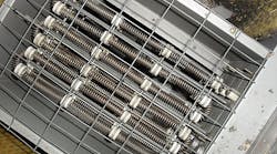
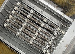
But it’s a very different process to apply the eight pages of Art. 424 requirements for fixed electrical space heaters. It helps to know how Art. 424 is organized (see SIDEBAR: Article 424 Organization). A key aspect is most of this Article is devoted to specific types of electric heaters. Part VI, for example, applies to duct heaters; these typically use a resistance heating coil (Photo).
Branch circuits
The individual branch circuit can supply any VA or wattage rating of fixed electric space-heating equipment for which it’s rated [424.3(A)]. An implication of this is that it often makes sense to put the heater equipment on its own circuit.
Compartmentalizing the design this way is often simpler, and it provides the ability to lock out the heater supply circuits. And if you want to meter or monitor the heater loads (e.g., with a building management system), dedicated circuits make even more sense.
But compartmentalizing doesn’t always make sense. For example, let’s say the application is an outbuilding that houses a fire pump 180 ft from the main building. The fire pump and jockey pump are on their own circuits. You’ve got two wall-mounted electric space heaters and a couple of overhead fluorescent light fixtures (320W total in lamps). In this case, it doesn’t make much sense to run a separate branch circuit all that way for the lights.
For the purposes of load calculation, consider the heater equipment to be continuous loads [424.3(B)]. So when determining the branch circuit size, you multiply the total heater equipment (and motors) load by 125% and then add the total of the noncontinuous loads to that number [210.20(A)].
Once you’ve determined the total load on the circuit, you can size the OCPD for it. But if the circuit supplies two or more fixed heater outlets, then the OCPD can be only 15A, 20A, 25A, or 30A [424.3(A)]. If the application isn’t a dwelling unit, then you can use a 50A OCPD.
Installation
The first requirement in Part II [Installation] is that you must install all of this equipment in an “approved manner.” But what does this really mean? Article 100 says “approved” means “acceptable to the authority having jurisdiction” (AHJ).
To begin with, the installation must comply with the applicable requirements from Chapters 1 through 3. For example, you must:
- Close unused openings in enclosures used in electric heating systems [110.12(A)] even though Art. 424 doesn’t specify this requirement.
- Meet all of the applicable branch circuit requirements in Art. 210, even if they don’t appear in 424.3 [Branch Circuits].
Part II provides additional requirements for AHJ acceptance. You can waive these only with special permission (from the AHJ) [424.10].
Check to see if the equipment you’re installing requires supply conductors with more than 60°C insulation. If it does, ensure those conductors are clearly and permanently marked [424.11], and the marking is visible after installation. This requirement is yet another reason to use a labeling device or system. These tools make it easier to meet conductor labeling requirements for all installations, not just heaters.
Your chosen routing path for your supply conductors may leave them subject to physical damage. If so, you must provide protection in an approved manner [424.12(A)]. To decipher that requirement, we go back to Art. 110. You can use only wiring methods (including raceway) recognized as suitable by the NEC [110.8]. If your solution consists of enclosing the conductors in something, don’t enclose the conductors in anything that’s not in Chapter 3.
If the location is damp or wet, use only heaters (and related equipment) listed for such locations [424.12(B)]. Would this apply to our fire pump room mentioned earlier? Walk into a typical fire pump room, and it’s usually dry as a bone. But if outside (as in our example), it can get damp (which is one reason for those heaters). And leaks happen. You don’t want the heaters to short out, so prudence leans toward considering this a damp, or even wet, location.
Before finalizing where you’ll mount the heater(s), determine what, if any, combustibles will be nearby so you can meet the space requirements for the heater(s) you’re installing [424.13]. If, for example, the heaters are keeping a warehouse from freezing, where will the combustible items be stored? How much space does heater model X need between it and combustibles?
If you can’t get a firm answer, you could install bollards to create a “no combustibles” zone in front of those heaters. Another option is to use a heater listed for direct contact with combustibles, but it might not be practical for the application.
Control and protection
Part III contains the requirements for disconnects, thermostats, and overcurrent protection. The disconnect requirements differ based on such factors as whether the:
- Heating equipment has supplementary overcurrent protection [424.19(A)] or not [424.19(B)].
- Heater has a motor more than 1/8 hp [424.19(A)(2), 424.19(B)(2)] or contains no motor more than 1/8 hp [424.19(A)(1), [424.19(B)(1)].
- Occupancy is one-family [424.19(C)(3)], two-family [424.19(C)(2)], multi-family [424.19(C)(1)], or some other type [424.19(C)(4)]
If you want a thermostat to serve as both controller and disconnect, it must meet four requirements. Mainly, it must directly open all ungrounded conductors when placed in the OFF position [424.20].
Some key requirements for overcurrent protection:
- OCPDs can’t be rated higher than 60A if protecting resistance-type heating elements.
- Circuits for resistance-type heating elements may have to be subdivided into 48A (or less) circuits; refer to 424.22(B) if your equipment is rated more than 48A.
- If your loads are subdivided, the field-wired conductors between the heater and the supplementary OCPDs must be sized at least 125% of the load served [424.22(E)].
- The conductors supplying the supplementary OCPDs are considered branch circuits (size them accordingly) [424.22(D)].
Types of heaters
Article 424 provides requirements for five types of electrical heating. Each type has its own Part; therefore, Parts V through IX are technology-specific.
These various types of heating systems differ enough that there’s no way to standardize the requirements among them. So if you’ve been installing duct heaters [Part VI], you can’t do heating cables the same way even though they’re both basically resistance heaters. Cables don’t have a fan circuit interlock [424.63], but duct heaters don’t come with the slew of requirements for surfaces that cables do.
Here’s a note on overcurrent protection for resistance-type boilers. Earlier, we mentioned that you may need to subdivide the heating elements into 48A (or less) circuits. You don’t have to do that if the vessel containing the heating elements is AMSE-rated and stamped [424.72(A)]. Fortunately, this exclusion is also referenced in 424.22(B).
Avoiding violations
Understanding the organization of Art. 424 makes things simpler, but don’t fall into the trap of oversimplifying. One requirement in particular is vague: You must protect the equipment in an approved manner where it’s subject to physical damage [424.12(A)].
To comply, you must first evaluate the physical damage threat and then implement physical protection to mitigate. It may not be enough that you installed the conductors in rigid metal conduit (RMC). Maybe you also need to place bollards in front of the heating unit. Think beyond minimal compliance to actually eliminating the threat.
Lamendola is an electrical consultant located in Merriam, Kan. He can be reached at [email protected].
SIDEBAR: Article 424 Organization
Part I — General requirements, same as other Articles.
Part II — Installation. These requirements are mechanical in nature.
Part III — Control and protection. Disconnects, overcurrent protection, thermostats, etc.
Part IV — Marking. This is for manufacturers. But it can help you spot counterfeit heaters, so look on the equipment for the required markings.
Part V — Space-heating cables. The cables heat up, providing heat to the surrounding area. The requirements deal mostly with clearances and location.
Part VI — Duct heaters. These requirements apply to any heater mounted in the air stream of a forced air system (unless the air-moving unit is part of an integral system). Duct heating systems typically come with finned, open coil, or tubular heating elements that are inserted into the duct flange-mounted on it.
Part VII — Resistance type boilers. Because these boilers use resistance-type heating elements, the elements are like an electric space heater except the “space” they heat is occupied by a liquid which then circulates through the occupancy through a system of pipes.
Part VIII — Electrode type boilers. Similar to a resistance type boiler heating system (circulating liquid), but current passes through electrodes to heat up the liquid.
Part IX — Radiant heating panels/panel sets. Modular panels, instead of a piping system. A key advantage is they can be zoned for individual rooms or spaces.
