Motors differ from other types of loads in one important way: The motor needs much more current to start than to run. This temporary, but significant, inrush current is what complicates motor circuit protection. The overcurrent protection device (OCPD) must accommodate inrush current while still protecting the conductors. The conductors must be able to handle and dissipate the short-term increase in heat from that starting current. Much of Art. 430 is concerned with getting both of these requirements right.
For other types of loads, a single device provides overcurrent protection and overload protection. Because of inrush, motor circuits handle those functions separately — that is, the job of protecting the conductors and the load gets split up for motor circuits. Fault protection opens the circuit when there’s a high level of excess current, such as from a fault or short circuit. But an overload is a relatively small amount of excess current. OCPDs protect against current in excess of the rated current of the equipment or ampacity of a conductor, whether it’s a motor circuit or not. Normally, the OCPD also handles overloads. But with motor circuits, separate thermal overloads do that.
As with any circuit, analyze the loads before sizing motor OCPDs and conductors. Here are some highlights:
1. If multiple motors are on the same feeder and/or branch circuits, look at load diversity. Do any of these operate in a mutually exclusive fashion?
2. Which loads are continuous? Noncontinuous?
3. Does the system include a variable-frequency drive (VFD)? Is it power-factor corrected? Does it have harmonics mitigation?
4. Do you need to derate conductors for voltage drop?
5. What type of motor(s) are you installing? For example, part-winding motors have additional requirements. Review Art. 430 Part I when making this assessment.
6. Is this application covered by another article [Table 430.5]?
Sizing motor circuit conductors
Normally, we size the OCPD and then the conductors. You find this order of calculation in the examples of Appendix D. But with motors, your second step is to size the conductors [Table 430.1].
Not coincidentally, the requirements are in Art. 430 Part II. In Part III, you’ll find the requirements for providing thermal protection to the motor; that’s outside the scope of this discussion. Part II applies to motors operating at under 600V, such as typical 480V industrial motors. If your motor operates at over 600V, use Part XI instead.
How you proceed depends on whether these conductors are for:
- Single motor. Apply 430.22. Then see if any of subsections (A) through (I) apply to your installation.
- Wound rotor secondary. Apply 430.23.
- More loads than just that motor. Apply 430.24.
- Combination load equipment. Apply 430.25.
- Motors with PF capacitors installed. Apply 430.27.
- Constant voltage DC motors. Apply 430.29.
If you have load diversity, you can apply a feeder demand factor [430.26]. If you’re using feeder taps, apply 430.28.
To make things simple, let’s assume you need to size the conductors for a single, continuous-duty 40HP motor. Those conductors must have an ampacity of at least 125% of the motor FLC. Use the FLC from the motor nameplate. If, for some reason, you can’t get this from the nameplate or the motor data sheet, use the applicable NEC table (e.g., Table 430.250). It’s best, however, to obtain the information from the motor manufacturer (and then affix a new nameplate to the motor).
Your motor’s nameplate says its FLC is 53A. Coincidentally, this is close to the 52A shown in Table 430.250. You now have a three-step process for sizing the conductors:
Step 1. Identify the table. You’re running three THHN conductors in intermediate metal conduit (IMC). Use Table 310.15(B)(16).
Step 2. Apply the temperature correction factor. Determine the maximum ambient temperature — not for where the motor is, but for where the conductors are running.
Suppose these will run overhead, and you know the maximum temperature will be 110°F (43°C).
From Table 310.15(B)(2)(b), you see you must multiply the allowable ampacity by 0.87. Alternatively, you can multiply 53A by 1.15, which gives you 61A.
But what if your ceiling temperature is, say, 160°F (71°C)? In the 60°C column, the ambient temperatures end at 55°C. In such a case, split the run; see Annex D3(a) for an example of how to do this.
Step 3. Size the conductor per the required ampacity. Using the 60°C column, you see this circuit requires a conductor at least 4 AWG.
OCPD sizing
Size the OCPD per 430 Part III, noting that you use the motor nameplate current rating (FLA), not the FLC [430.6(A)].
In our example, you sized the conductors for a single motor that has 53A FLC. Let’s assume the motor is on its own branch circuit. How do you size the OCPD for that circuit? The answer is in 430.52. How would you know to go there? Earlier, you referred to Table 430.1 to see what your second step is. Go back to Table 430.1 as you continue to work out your motor requirements. For this step, Table 430.1 directs you to Part IV.
There, you’ll read that the OCPD must be capable of carrying the starting current of the motor [430.52(B)]. This doesn’t mean you size the OCPD for the starting current, however. The meaning of this emerges in 430.52(C). You need to specify an OCPD per Table 430.52.
When you size the overload, you use the FLA. But to size the OCPD, you use the FLC. First, find your motor type and OCPD type in Table 430.52. Then, multiply your FLC by the percentage of FLC required by the chart.
Using the 53A FLC of our example with an inverse time breaker, you multiply the FLC by 2.5 for a maximum rating of 132.5A. This isn’t a standard OCPD size [240.6(A)]. Since 430.52(C)(1) says the OCPD can’t exceed this calculated value, do you use the next size down? If you read on just a bit, you’ll see that Exception No. 1 lets you use the next size up. So for this branch circuit, you need a 150A breaker.
If it turns out that the breaker trips every time you try to start the motor, then what? Determine if the trip is due to a fault or from overload. If it’s overload, Exception No. 2 lets you use a larger OCPD.
But there are limits to how big that OCPD can be. You may have voltage drop or power factor problems that lead to excess starting current. In addition to correcting these, consider a soft-start or VFD so you eliminate across-the-line starting. A big advantage of using a soft-start or VFD is you eliminate a common cause of cable failure. The power anomalies resulting from across the line starting can damage loads on other feeders, not just the motor system.
Multiple loads
Now let’s change our example slightly. Suppose this motor is on a branch circuit with two other motors and four electric heaters. The loads are 40A, 27A, and 40A, respectively. How do you size the OCPD?
Unless you have a compelling reason to put these loads on the same branch circuit, it’s generally best to put each motor on its own branch circuit.
First, analyze the loads. If that 40A motor runs an HVAC compressor, you can disregard the 40A heaters; these are mutually exclusive loads. To see why not to disregard the motor instead, review the calculations we just did.
Next, turn to 430.53. The first requirement is that you must use fuses or inverse time circuit breakers. So when you use Table 430.52, ignore the two middle columns. Apply Table 430.52 to the sum of your motor loads, then add to the sum of the other loads.
For feeder OCPD requirements, turn to Part V. The key here is the “don’t exceed the rating” requirement of 430.52(C)(1) applies only to the largest load.
For the conductor requirements on that feeder, turn to Part II. To determine the minimum conductor ampacity [430.24]:
- Multiply the FLC of the largest motor by 125%.
- Add up the FLCs of the other motors.
- Multiply the continuous non-motor loads by 125%.
- Add up all of the above to the total of the non-continuous loads.
Avoiding confusion
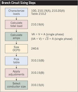
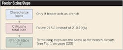
To size conductors and OCPDs for branch circuits, follow the steps shown in Fig. 1. The steps for feeders modify the steps for branch circuits, as shown in Fig. 2. But if you have motor circuits, remember that the inrush current of motors changes things:
- The normal functions of the OCPD are split. With motors, you have an additional device that does the overload protection job normally done by the OCPD.
- You use multipliers for sizing the conductors (125%) and the OCPDs [Table 430.52].
If you understand the branch circuit conductor and OCPD sizing steps, it’s just a matter of modifying them a bit for feeders and/or motors.
Lamendola is an electrical consultant based in Merriam, Kan. He can be reached at [email protected]
