In general terms, dimmers are devices that vary light level (intensity) of lamps by controlling the amount of power that is delivered to the lamp. Dimming can be controlled by either manual or automatic means.
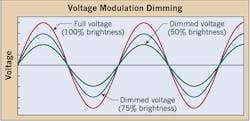
There are two methods of dimming: reducing the voltage applied (i.e., voltage modulation), as shown in Fig. 1, to the lamp and reducing the amount of time that full voltage is applied to the lamp (i.e., phase control). The applicable dimming method must be compatible with the lamp type. This article will focus on phase control.
Incandescent lamps respond well to almost all types of dimmer technology. Although incandescent lamps remain widely used and still have a purpose in overall lighting design, they tend to consume the most energy and return the lowest efficacy (i.e., lumens per watt). The use of dimmers with incandescent lamps can reduce their energy consumption and increase lamp life. Because incandescent lamps use resistive filaments, they can be dimmed by electronic dimmers with little to no problems. This has lulled many electrical workers into thinking lamps that use reactive methods of starting (e.g., fluorescent, HID, and LED) can be controlled by the same dimmers that controlled incandescent lamps. In some respects, they would be half right with this assumption.
Special care must be taken when dimming low-voltage lighting systems that use coil and core transformers, fluorescent and HID lighting systems that use a ballast, and LEDs that use drivers (electronic transformers). Dimmers rated for incandescent dimming only can’t be used to dim low-voltage lighting systems, nor can they be used to dim fluorescent and HID lighting systems.
Low-voltage dimming of incandescent lamps must take into account the transformer used to supply these lamps. Two types of transformers are used to supply low-voltage lighting systems:
1) Magnetic (traditional, wire wound around a laminated steel core), and
2) Electronic (solid-state).
Dimmers used for low-voltage lighting are rated in volt-amps (VA). The dimmer must be selected for the type of transformers used in the low-voltage lighting system. Dimmers designed for magnetic transformers protect the transformer from the application of any DC voltages that would cause overheating and damage. They must also withstand any voltage spikes and surges that may come from the line side and not pass them on to the transformer. Lighting systems that use electronic transformers must use dimmers designed for these types of transformers. An advantage to electronic low-voltage dimming of electronic transformers is their silent operation over the entire dimming range. However, electronic transformers have limited output, usually 150W or less. On the other hand, low-voltage magnetic transformers can be designed to handle loads as high as 10,000W.
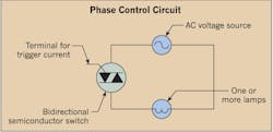
To accomplish dimming of low-voltage magnetic or electronic transformers requires two different types of dimmer control technology. A triac or thyristor-type dimmer (Fig. 2) is used for resistive and inductive loads, such as incandescent, neon, cold cathode, and low-voltage (inductive/magnetic) lamp sources. Dimmers used to control these types of loads are known as leading edge (LE) or forward-phase control (FPC) dimmers. Dimmers that are used to control electronic transformers have a different switching characteristic and are known as trailing edge (TE) or reverse-phase control (RPC) dimmers. It’s important that you select the right dimmer for the load type. The need for the two dimming waveforms is a result of the drive requirements of different load types. To understand this further, a little review of AC theory is in order.
When AC voltage is applied to an incandescent lamp, which has a resistive characteristic, the voltage and current waveforms are almost identical. They are said to be “in phase.” A wire-wound transformer, however, is an inductive load, and the current tends to lag behind the voltage in an AC circuit. On the other hand, the AC inputs to the electronic transformers are usually capacitive, which causes a leading power factor to be seen by the dimmer. If the wrong dimmer is selected for the load, these leading/lagging currents create issues for a dimmer as to when to turn on and when to turn off within the AC waveform.
For leading-edge dimmers, once triggered, a triac or thyristor relies on the current flowing through the device to keep it conducting. If the current falls below the device’s threshold level (i.e., the zero crossings of the AC waveform), it will turn off and stop conducting. However, with an inductive load, the current lags behind the voltage so it’s possible that the current through the triac will not reach the triac’s threshold level before the trigger pulse ends. This results in unacceptable dimming performance. To avoid this issue, dimmers designed for use with wire-wound transformer loads use a triggering technique known as a “hard firing.” This ensures the trigger pulse is maintained for a long enough period of time to make certain that the current reaches the device’s threshold level. Magnetic wire-wound, low-voltage loads can only be dimmed using a leading-edge waveform dimming device (Fig. 3).
Electronic low-voltage loads tend to have a capacitive input (i.e., current leading the voltage) and require a trailing-edge waveform for dimming. TE or RPC dimmers use transistors such as FETs or IGBTs as the power device instead of the typical triac or SCR devices used in leading-edge dimmers. The transistors allow the circuit to apply or interrupt current anywhere in the AC waveform. A triac or SCR device can only be controlled to turn on at a predetermined point. The “turn off” of these thyristor devices is only controlled when the load current goes through a zero crossing of the AC waveform. A TE dimmer applies line-voltage to the load beginning at the zero crossing. Then the power device switches off at some point in the half cycle, creating a TE waveform (Fig. 4). Note: As mentioned above, incandescent loads can be driven by either dimming waveform.
Understanding the lamp type is key to understanding dimmer selection. Get this right, and you’ll have a bright future in lighting control.
Coleman is director of telecommunications curriculum development and training with the electrical training ALLIANCE in Upper Marlboro, Md. He can be reached at [email protected].


