To understand a series circuit, visualize it. You can do that by making a drawing. Just draw a box, to start with. This box represents your circuit. Notice there is only one path: the perimeter of the box. At the bottom of the box, erase a small portion and drop a symbol in there for the power supply.
Now you need to draw in at least one load so you don’t have a short circuit. Just as with the power supply, erase a spot but instead of a power supply symbol add a load symbol. A resistor or motor would work fine, depending upon how artistic you feel like being.
If you were to add a load on the left side of this box, a load on the top, and a load on the right, all three loads would be in series. Take out any load, and the current flow stops because now you have an open circuit.
The series circuit is a single closed loop, as you can see. But a parallel circuit provides multiple loops.
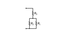
If you stack the loads on top of each other ladder-rung-style in your drawing, they are in parallel. You can remove one and not open the circuit for the other two. This is a parallel circuit.
In a series circuit, you don’t have the full supply voltage at each load. Each load in a series circuit gets a share of the supply voltage. That’s one reason we don’t wire building circuits in series.
The voltage divides in proportion to the load; the higher the impedance of each load relative to the others, the greater the proportion of the supply voltage you will see on that particular load.
If one load is 50 ohms and the other is 150 ohms, the first load will get 25 percent of the supply voltage and the second will get 75%.
Because our typical building loads are rated for a nominal supply voltage, we wire building power circuits in parallel. This way, each 277V light on lighting circuit actually gets 277V from that 480/277V transformer/panel and each 120V receptacle has 120V instead of fighting for the voltage with the other loads (and all loads losing the fight).
Another reason for not wiring our loads in series is if a particular load fails open, the flow of power in that circuit stops. If you ever played “find the bad bulb” with those old-style Christmas tree lights, you can only imagine how this would play out for an industrial facility.
So we use parallel circuits for power and (generally) series circuits for control. In some cases, control circuits use a parallel configuration. Consider the common example of wiring up a three-way light switch system.
Suppose you have two light switches. If you wire them in series, opening either switch shuts the light off. However, both switches must be on for the lights to come on. That’s pretty inconvenient, though you could have a reason for doing this. Many safety circuits are wired this way, for example.
The way we actually wire a three-way switch is by using a “traveler wire.” This sets up a hybrid (series-parallel) circuit that permits either switch to operate the light.


