Over the last 50 years, self-regulating heater cables have had a significant impact on the industrial and commercial industries. This invention modernized the application of electric cables for heating, which had previously seen minimal advancement. Many electrical professionals are familiar with self-regulating heater cables, yet few understand exactly how they function. The explanation often heard is “you put it on the pipe, and it just works.” This article provides a brief history of this groundbreaking invention as well as a fundamental understanding of the construction and application of this type of heater cable.
Cable history
The history of electric cables for heating dates back to 1896, when a patent was filed for mineral-insulated (MI) cable. At this time, MI cables were used only for power and control circuits for critical equipment, but they laid the groundwork for heater cables. It was not until the 1930s that this technology was considered for and developed as a cable to be utilized for heating.
MI cable construction was extremely robust and capable of very high watt-densities. The drawbacks to this type of heater cable are the same today as they were back then. Due to their series-resistance design, these products must be manufactured to a specific length to achieve a specific heat output. In addition, they require particular attention to proper installation techniques to prevent overheating and burnout. Lastly, while field-repairing an MI cable is possible, it requires specialized training and is not consistently successful. For these reasons, utilizing electric cables for heating failed to gain a significant advantage over the traditional use of steam for heat-tracing applications. For approximately 30 years, steam tracing and electric MI cables continued to be the standard options when piping or equipment required external heating.
During the early 1970s, experiments with conductive polymers and radiation chemistry led to the invention (and patent) of the first commercially successful self-regulating heating cable. This new heater cable was of polymer construction and entirely different from its metal-clad MI cable predecessor. The cable consisted of a high-carbon-content polymer core, which was extruded between two bus wires. This core allowed the cable to vary its heat output along the entire length of the cable (creating the self-regulating feature).
This new cable also had a parallel circuit design that allowed the cable to be cut in the field to the exact length required. This development alone was significant as the time for field-measuring and custom fabrication were no longer required. Finally, the success of this heater cable could not have been possible without the incorporation of radiation technology, which was used to cross-link the polymer core. As the heater cable’s core matrix is temperature-cycled, its chemical composition is altered. The heater cable required the ability to maintain its original resistance as the cable cooled. This was possible only by exposing the heater cable to an electron beam that would cross-link the polymer core, essentially giving it an “elastic memory” that resulted in a highly stable device. After cross-linking, the heater cable exhibited extremely predictable sheath temperatures when power was applied. This predictability was critical for testing and certifications, as the self-regulating heater cable could then be certified with a known maximum temperature rating (T-Rating) for installations within hazardous areas.
Self-regulating heater cables vary in power output, temperature exposure range, and even construction. As monolithic core technology is, by far, the most common construction method for self-regulating cables, the following discussion focuses on this cable type.
Cable construction
As outlined above, self-regulating heater cables consist of a high-carbon-content polymer core that is extruded over two bus wires (see the Figure). Bus wire varies in size from 18 AWG to 14 AWG and is generally nickel-plated copper. The core consists of a highly specific combination of carbon black and polymers with the exact mixture dependent on the output of the cable and manufacturer.
Cables constructed with polyolefin that will be utilized at lower maintain temperatures (generally 150°F and below) have a core that either chemicals or irradiation must cross-link before functioning properly. Chemical cross-linking is generally no longer performed due to quality concerns. The purpose of the cross-linking process is to bond the carbon molecules together in chains. This bond creates multiple conductive paths within the core and is the heart of this heating technology. Cross-linking is achieved by subjecting the core to an electron beam accelerator multiple times until these bonds are fully formed.
Generally, cables constructed with a fluoropolymer will maintain temperatures above 150°F, do not require cross-linking, and the carbon is simply compounded with the polymer before extrusion. A dielectric insulation jacket is then extruded over the core and bus wires.
For the “first generation” self-regulating cables, this is where the cable construction stopped. As federal, state, and local electrical codes were updated, a new requirement was established mandating the heater cable have a grounding conductor. The result was a metallic ground braid to be wrapped around the dielectric insulation jacket. A final over jacket of polyolefin or fluoropolymer is then applied over the braid to complete the cable. This final over jacket has the cable’s properties printed on it for easy product identification.
Cable operation
Self-regulating heater cables operate by applying a voltage to the bus wires of the cable. Until recently, most cables were capable of utilizing only up to 277VAC single-phase power. Recent advances in technology have resulted in cables that can now utilize 480VAC single-phase power. The applied voltage is consistent throughout the length of the cable (not accounting for voltage drop), which energizes the multiple conductive paths created within the carbon core. The cable core has a positive-temperature coefficient, meaning as temperature increases, the overall resistance of the cable core also increases. This allows the cable to change its heat output in response to either external heat or internally created heat. The increased resistance is created by the thermal expansion of the core, which reduces the number of conductive paths. This increase in resistance results in lower power output at higher temperatures and higher power output at lower temperatures.
Cable applications
While there are various types of heat tracing cables to choose from, self-regulating cables are often preferred because they are considered the “safe” heater cable. Due to the cable’s ability to limit power output in response to external temperature, a natural safety margin to prevent overheating of the product or cable itself is introduced. Self-regulating cables are subjected to rigorous testing to determine the “stabilized” temperature of each cable type. This is the maximum surface temperature that will be reached by the cable’s over jacket under the most extreme conditions. By establishing this maximum temperature, a T-Code can then be formally established for a given watt-density cable. This certified T-Code rating is extremely useful when designing heater cables for use within a hazardous area.
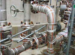
Installation of the self-regulating heater cable is similar to other types of heater cables. The cable is typically attached to process piping with a self-adhesive glass fiber tape (see Photo). For attaching to equipment or other irregular surfaces, it is common to apply self-adhesive aluminum tape on top of the heater cable.
In contrast to series-resistance type cables, self-regulating cables may overlap onto themselves without the risk of overheating and burning out at the point of contact. This is beneficial when a large quantity of cable must be placed onto a valve or other item with limited surface area.
Control of self-regulating heater cables is also similar to that of other cable types, utilizing either thermostat or microprocessor-based control methods. With careful design, self-regulating cables are capable of being energized without traditional controls, allowing them to remain energized continuously. Although an uncontrolled installation is generally not recommended, it is possible due to the self-regulating effect, which allows the cable to maintain the required temperature without overheating the product or exceeding area temperature limitations.
Wrapping it up
Self-regulating cables provide a relatively safe and flexible solution to heat-tracing requirements with benefits realized beginning in the design and extending through installation, operation, and maintenance. These cables are widely accepted and often specified because they can provide solutions for most heating needs. While they cannot replace MI cables when higher temperatures must be addressed, research and development on this technology are ongoing.
Randal Schultz is a fellow in the Electrical Engineering department of Fluor, Sugar Land, Texas. He possesses extensive technical expertise with electric heat tracing in the petrochemical and power generation industry. With more than 25 years of experience dedicated to electric heat tracing, he has performed design, installation, consulting, and troubleshooting for numerous new and revamped facilities. He can be reached at [email protected].
Mukesh Singhal is an SME (Electrical Heat Tracing) in the electrical department of Fluor in the New Delhi office. He possesses technical expertise with electrical heat tracing in the petrochemical and refinery project. He has 18 years of experience (including 14 years in electrical heat tracing) and has performed estimation, design, and engineering in FEED, detailed design for various greenfield and brownfield projects. He can be reached at [email protected].
Troy Ranney is an account manager with Thermon, Inc. in Houston. He possesses extensive technical expertise specific to heat tracing across various industries. With more than 17 years of experience dedicated to various heat trace technologies, he has performed design, installation/construction, consulting, and troubleshooting for numerous new and revamped facilities. He can be reached at [email protected].


