Among the things that contribute to satisfaction, good reputation, and a thriving business on the part of an electrical contractor would be a collection of projects that are still operating reliably 40 or 50 years after they were first put into service. Of special merit would be jobs that had significant installation of medium-voltage (MV) power cables. Large, campus-type projects that involve 5kV, 15kV, or even 35kV class power cables can be a challenge to bring to successful completion — where one might consider “success” as a system that has not required call-backs or warranty action for “infant mortality” failures on the equipment and devices installed.
What makes the difference between an installation that experiences problems only days or weeks after power-up and one that continues to operate well past its “useful life?” The experienced electrical contractor already knows the answer — good quality materials and best-quality work practices.
Installation of MV cables is an area where attention to detail is essential. This article will address MV cable features and pitfalls in general, and also focus on an often overlooked item: MV cable shielding conductors.
Why use shielded MV cable?
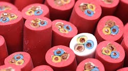
Shielded power cables are the key to a safe and reliable means of containing and transporting MV electrical power (Fig. 1).
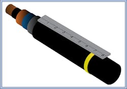
The outer shielding system for most modern cables consists of two components. There is a conductive shield material, either fine wires or copper tape over a semiconductive screen, which is applied to the surface of the true insulating material. The outer jacket is not really insulation, but more of a covering to protect against physical damage, contamination, and moisture. The shielding system performs the following functions:
- Confines the electric field within the cable.
- Forces a symmetrical radial distribution of voltage stress within the dielectric.
- Protects the cable from induced potentials.
- Limits radio interference.
- Reduces (but may not necessarily eliminate) the hazard of electrical shock to personnel.
- Provides a ground path for leakage, charging, stray, and fault currents.
Let’s focus on the first two bullet points. The metallic copper tape shield conductor(s) must be effectively grounded to perform those functions. Unless there are unusual circumstances that give rise to unwanted circulating currents through the shields, each cable shield should be solidly grounded at both ends of the cable run. Best practices suggested by the cable manufacturer include grounding the shields at the splices (if any) as well, as noted in the “Engineering Handbook – 2018 Edition” published by The Okonite Company. Some owner’s engineers and some authorities having jurisdiction (AHJs) may insist on this practice. Others may be satisfied with proven shield continuity between both ends of the run and proper grounding at those ends. The symmetrical (with emphasis on symmetrical — more on this later) radial distribution of voltage stress is a factor for long-term, reliable operation. When the stress is controlled within the limits of the insulation material, degradation with age is minimal.
Installation Essentials
Proper installation practices are critical to MV cable longevity. The installing contractor cannot control possible defects in the manufacturing of the cables, nor what those cables will be subjected to over their service life, such as unfavorable ambient conditions or frequent overloading. Nevertheless, there are plenty of aspects and details that can be controlled and monitored. First among these is the quality of the raceway.
Whether metallic or nonmetallic, exposed or buried in earth or duct banks, the raceways must be clean and free of burrs or other sharp surfaces before cable is pulled in. But that’s not all. If buried, is the trench uniform? Although the run may be considered “straight” from one location to another, things may become complicated due to numerous dips and rises throughout the run. This applies to direct burial installations also. Naturally, the manufacturer recommends pulling arrangements, segment lengths, and direction that result in the least tension, according to Prysmian's Wire and Cable Engineering Guide.
The consequence of dips, grade changes, and bends in the raceways is an increase in pulling tension during installation. One reason for this recommendation is the expected limitation due to sidewall bearing pressure when the cable must be pulled through bends. Each manufacturer publishes a minimum bending radius for the type of cable selected, which may range from four to 15 times the cable diameter. Many runs may have to include bends with a much larger radius than the minimum stated by the manufacturer. There are no universal parameters for this. The installer should always consult the manufacturer for limits on the type of cable being used. Other guidelines in various sections of the National Electrical Code (NEC) [Art. 300] should also be kept in mind.
Avoid pitfalls
Bad things happen when the bending radius is insufficient or the sidewall pressure is too high. Severe sidewall pressure can distort the cable structure, making it somewhat oval rather than round. This changes the internal voltage stress and tends to concentrate more stress on the thinner insulation thickness toward the flattened areas. If separation has occurred within these components, this may create voids, which worsens the situation. Finally, the shield conductor(s) may be distorted or separated, which may leave gaps in the coverage or — worse yet — some of the strands may be broken.
Static sidewall pressure, which occurs after pulling is completed, subjects the cable to a continuous force that tends to flatten the cable walls. Static sidewall pressure limits can be surprisingly low. This problem occurs where the cable(s) rest against a bend at the top of a slope or vertical run and the continuous pull from gravity has not been properly relieved. This condition will severely affect the useful service life of MV cables.
The installer has two tools available to them to protect against such pitfalls. The first is to plan the pull and monitor the pulling tension carefully for every segment. The second is not to ignore the test results. Whether the installer uses qualified in-house personnel or the services of an independent testing agency, proper interpretation of the post-installation electrical test results is important. This is more than a “go/no go” test. It helps analyze the quality of the cable and the installation effort as one entity. High-potential DC tests should always be applied before cable splicing activities begin per the ANSI/NETA Standard for Acceptance Testing Specifications for Electrical Power Equipment and Systems, 2021 edition.
The importance of splicing
Splicing is another area where the contractor must pay close attention to their work. Proper splicing techniques cannot be underestimated. Whether “classical” tape, hot or cold-shrinkable sleeves, rubber compounds, or resin molds are used, the splices should be prepared, cleaned, and properly joined with the same quality as the cable was manufactured. In effect, the splice should be constructed like you’re building a piece of cable in the field. As outlined in the Power Cable Splicing and Terminating Guide from 3M, the general process is as follows:
- Prepare the critical surfaces so they’re clean and free of contamination.
- Join the current-carrying conductors with appropriate connectors (butt splice).
- Re-insulate the areas.
- Re-shield the insulation.
- Re-jacket the overall assembly.
Remember, every step you take should be done to reduce and control voltage stresses in the disturbed area of the splice. Don’t “guesstimate.” Measure accurately and follow the manufacturer’s instructions to the letter. (Fig. 2).
The energized electric field is unforgiving. It will eventually find a way through any errors — even if post-installation test results appear to be reasonable.
After all splices have been completed, acceptance testing should be undertaken for all the cable runs before source and load terminations are made. The extent of such tests may be mandated by the contract specifications; but where these are vague or may fall short, the installer needs to make a business decision. For example, if the project only calls for 100 ft of 1/0 AWG, 15kV cable between the electric utility and the service entrance equipment, perhaps a single high potential test and inspection of the termination quality may suffice. On the other hand, if the installer has invested in miles of 500kcmil, 15kV cable with many splices, along with exceedingly difficult access, it might be in the company’s best interest to apply all of the NETA recommended acceptance tests, regardless of what the project specifications might require.
Use of an effective ground conductor
At this point, we’ve outlined the need for proper installation and handling of MV cables, including the testing of shield continuity and the effective grounding of the shields. We now need to consider the use of an effective ground conductor.
R. H. Kaufmann and some test engineers and technicians at General Electric performed an investigation decades ago for what was then considered adequate means of carrying ground continuity between equipment. Their goal was not to derive a bunch of equations but rather understand how ground-fault current wanted to return to the source. Their test setup was 100 ft of rigid galvanized steel (RGS) conduit installed on a wall of a short circuit test lab and attached to the building steel with an adequate ground grid system underneath. The raceway had several 4/0 AWG cables, which were subjected to fault currents between 10kA and 12kA for 0.25 sec while high-speed measurements were made. The team subjected this arrangement to various ground-fault configurations. The conclusion was clear: The return conductor(s) nearest the faulted phase conductor always took the bulk of the return current. So, what conductor is closer to the phase conductor than the shields? None. That included the RGS conduit as a ground conductor. The ground grid system came in dead last.
As an installer, one might encounter a case where the cable and conduit schedule is unclear about the ground conductor in an MV cable run, thereby implying that the shields can act as that conductor. Can the shield be used as a ground conductor? What does the NEC say about it? The answer to the first question is maybe; the answer to the second can be found in Sec. 250.190(C). Let’s examine two examples:
Example 1: Suppose an end-user owns their service-entrance substation with two (2), 5,000kVA transformers rated 69kV/13.8kV, which are neutral resistance grounded via 100A, 10-sec resistors. Furthermore, suppose there is a significant run of non-metallic (PVC) raceway in a duct bank with 15kV class MV cables that connect to a bus tie breaker between these two supply buses, and no additional grounding conductor is mentioned. For this application, the NEC would allow the shields to act as grounding conductors. The practice is allowed in this case because the total ground-fault current is limited to 100A in all parts of the circuit.
Example 2: Consider the same main-tie-main configuration as in Example 1 using a service entrance switchgear, but this time each source comes directly from a 3-phase, 4-wire electric utility line. It is a safe bet to assume the source is solidly grounded (as most utilities use solidly grounded MV distribution whether aerial lines or underground cabling with concentric or jacketed concentric neutrals), which means the single line to ground (SLG) fault current will be substantial. That is why the NEC forbids shields to be used in such cases. As a conscientious installer, it might be time to write a request for information (RFI) to the owner or engineer if there is any doubt about the matter.
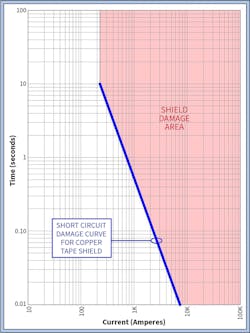
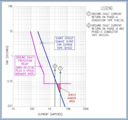
The reasons to avoid excessive ground-fault current on the shields are obvious from Fig. 3.
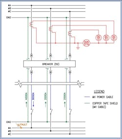
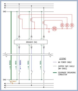
If a phase-A SLG fault were to occur at downstream equipment, the ground fault return and consequent tape shield damage on Phase-A cables would also affect Phase-B and Phase-C cables (see Fig. 4 for ground-fault current flow). Damaged shields and insulation mean that the entire affected run of cable is compromised and must be replaced.
Such damage can occur even with very short tripping times from an ANSI 50/51N (residual neutral overcurrent) or 50/51G (zero-sequence overcurrent) ground-fault protection device (see Fig. 5 for tape shield damage).
The solution is to ensure success by including an equipment grounding conductor (EGC), whether bare or insulated, as part of the bundle of MV cables being pulled. Although the NEC mandates the minimum size, a larger size ground conductor may be advisable. What we are trying to accomplish is to shunt as much current away from the shields as possible; the only way to accomplish that is by providing a parallel path with a reactance that competes with the shields themselves. The additional EGC must be within the bundle. The use of metallic conduits or ground conductors in a separate raceway (an afterthought) is ineffective and of little help with this problem. Strategically sizing the ground conductor also ensures that it will not reach a destructive temperature before the ground-fault protection device(s) trip the circuit. A coordination study helps determine what is needed.
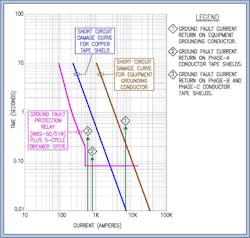
It is nearly impossible to predict how multiple shield conductors in parallel will share the ground-fault return current due to the installation variables and the number and quality of grounding points but adding a low reactance and lower resistance parallel path by the use of an equipment grounding conductor will certainly help guard against thermal damage. Figure 6 and Fig. 7 depict the ground current flow and corresponding reduced copper tape shield damage curve when using an adequately sized EGC.
That’s a wrap
We have emphasized that proper selection, handling, installation practices, and splicing skills are essential to successful MV cable function. We have examined the reasons why grounding conductors are a wise choice when shielded cables are installed in non-metallic raceways. Careful consideration of these means and methods will give the MV cable distribution system part of the installer’s project a fighting chance in the battle for longevity.
Alan L. Cinsavich is a senior electrical engineer with Helios Electric. Priyan De Silva is a senior electrical engineer with Helios Electric. They can be reached at [email protected].