According to the IEEE Buff Book, "A power cable must be protected from overheating due to excessive short-circuit current flowing in its conductor," which may damage or destroy the insulation. It also says, "The shield of the cable beyond the fault also carries part of the fault return current, which may then return along the shields of other conductors or equipment-grounding conductors, from common grounding points."
How can you verify that a power cable's shield will be able to carry a fault current of specific magnitude in the time needed for operation of a fault-current protection device without damaging cable insulation? Let's take a closer look.
Analyzing ground-fault current-carrying capacity
The typical medium-voltage (MV) feeder consists of a conduit or raceway, three shielded phase conductors, and a ground conductor. If one of the phases sustains a line-to-ground fault, the return fault current will divide itself among the metallic shields, ground conductor, and raceway (if metallic). The magnitude of current flow in each of these paths will vary inversely as to the impedance of the specific path. In other words, the higher the impedance of the specific ground path, the less amount of fault current will flow in that ground path.
The common belief is that most of the ground-fault current returns on the faulted phase shield. This is true if the ground fault is from a conductor to its own metallic shield. However, testing has shown that only 3% to 14% of the available ground-fault current will flow through each cable metallic shield.
The Table lists the measured current distributions during 400A ground-fault tests for various conduit-cable-ground wire configurations. The sum of the currents shown adds to more than 100% due to phase-angle differences in currents. As you can see, the percentages shown in the Table vary with the cable-conduit-ground wire configuration of the tested feeder. The Table also shows that the majority of fault return current will flow in the metallic conduit and ground wire, because their impedances are much lower than that of typical shielding constructions.
For ground-fault coordination study purposes, you can safely assume that 15% of the available fault current will flow in each metallic shield.
Verifying shield performance
ICEA P-45-482, "Short Circuit Performance of Metallic Shields and Sheaths on Insulated Cables," a standard published by the Insulated Cable Engineers Association, provides an equation you can use to determine the required cross-sectional area of the metallic shield of both 100%- and 133%-rated MV power cables:
M2 = IO2 t ÷ A2 (Eq. 1)
where IO = fault current (amperes)
t = time of fault (seconds)
A = effective cross-sectional area of shield (cm)
M = constant
Depending on the MV cable voltage rating, configuration, and construction, the constant M will vary. For 90°C-rated MV power cables with copper shielding and thermoplastic jacket (PVC or thermoplastic CPE), or impregnated paper insulation, the constant M is as follows:
-
0.063 for 5kV through 15kV- and 25kV-rated cables
-
0.065 for 35kV- to 46kV-rated cables
-
0.066 for 69kV-rated cables
For 90°C-rated power cables with copper shielding and thermoset jacket [Neoprene, Hypalon, or thermoset polyethylene (CPE)], the constant M is as follows:
-
0.089 for 5kV through 15kV- and 25kV-rated cables
-
0.090 for 35kV- to 46kV-rated cables
-
0.091 for 69kV-rated cables
By inserting any known two of the three variables in Equation 1, you can verify that the copper shield in each of your MV feeders is capable of carrying its portion of fault current within the time requirements dictated by the respective ground-fault relay or overcurrent protection device.
To find out various performance characteristics of your proposed shield construction, insert the proper value for the constant M into the ICEA equation, and then solve this equation for the characteristic in question. For example, if you want to know the maximum amount of time (t) that a given fault current (IO) can flow in a given shield, take Equation 1 and solve it for t:
t = (MA÷ IO)2 (Eq. 2)
Standard vs. special shield configurations
You can also determine the maximum fault current (IO) that can flow in a given shield for a given amount of time (t) by taking Equation 1 and solving for IO:
IO = MA ÷ √t (Eq. 3)
Or, you can determine the shield effective cross-sectional area (A) required to withstand a given fault current (IO) for a given time (t) by taking Equation 1 and solving for A:
Short-circuit current coordination example
A = (IO x √t ) ÷ M (Eq. 4)
You may find that standard shield constructions may not have sufficient cross-sectional area to handle the fault current for the cable in question. In this situation, you can then consider the following construction options that may satisfy the more demanding requirement:
-
14 AWG concentric wire strands in lieu of the standard 18 AWG sizing.
-
Helically applied 5-mil tape with 17% overlap.
-
One layer of overlapped, helically applied, 5-mil tape plus a second layer of reverse lay overlapped, helically applied, 5-mil tape.
-
Corrugated longitudinal 8-mil tape.
You can get effective cross-sectional area values for each of the above constructions, per cable size, from the cable manufacturer. By plugging this information into Equations 2, 3, or 4, you will obtain the best option for the specific feeder in question.
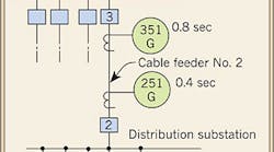
Figure 1 shows a single-line diagram of a typical MV distribution system, where a distribution substation is fed by cable from a main switchgear lineup. Ground-fault protective relays are also shown. Let's analyze this system closer.
What would happen if Relay 50G (for Feeder No. 1) fails? The answer is that Relay 251G would have to clear the fault before the shield in Feeder No. 1 is damaged.
Sustained Overvoltages and MV Cable Ratings Shielding
Looking upstream of Relay 50G, we see that the operating time of Relay 251G at maximum ground fault is 0.4 sec. With Relay 50G's operating time of 0.1 sec, Feeder No. 1's shield must be capable of withstanding its portion of the total ground-fault current of 1,000A for 0.5 sec without sustaining damage. This portion is 15% of 1,000A, or 150A.
Suppose Feeder No. 1 consists of three No. 4/0 AWG, 15kV, shielded conductors in a rigid steel conduit without a ground wire. Its shield must be able to withstand 150A of ground-fault current for 0.5 sec. Similarly, Feeder No. 2 shield must withstand 150A of ground-fault current for 1.3 sec (0.5 sec for Feeder No. 1 plus 0.8 sec for operation of Relay 351G).
By inserting these ground-fault current and time duration values into Equation 4, you can determine the required shield circular mil area. By comparing this value with the actual shield circular mil area of the cable in question, you can confirm the adequacy of the shield construction.
In situations where numerous calculations are required, especially in coordination studies involving many MV feeders, you can use shield withstand-limit curves that you can prepare yourself. Here's how to go about it:
-
Obtain actual circular mil area values of metallic shields per cable voltage and shield and cable construction.
-
Plug in these values, along with either incremental time values or ground-fault current values, into Equations 2 or 3.
-
Plot the solutions on log-log graph paper to form a specific shield withstand-limit curve, an example of which is shown in Fig. 2 (click here to see Fig. 2).
By verifying that the required shield withstand falls below and to the left of the limit curve, you confirm the adequacy of the proposed shield construction.
The shield withstand curve shown here is that of a 4/0 AWG, 15kV, grounded, concentric wire strand shielded MV power cable. The dotted lines represent the required shield withstand limits of Feeder No. 1 and Feeder No. 2. Note that the required withstand limits fall within the performance characteristics of the shielding configuration used in the feeders.
Medium-voltage (MV) power cables can also be damaged by sustained overvoltages, such as during a ground fault in one phase. This is why they bear a rating called "percent insulation level," or "%IL." The %IL ratings include the following:
-
100%IL — Cables that may not be required to operate longer than 1 minute in case of a ground fault.
-
133%IL — Cables that may not be required to operate longer than 1 hour in case of a ground fault.
-
173%IL — Cables that may not be required to operate longer than 1 hour continuously with one phase conductor grounded.
Generally, you would set the timing of permissible protective systems in accordance with the IL rating of the cables involved.
Sidebar: Other Functions of MV Power Cable Shielding
The ground-potential metallic shield of an MV power cable serves to protect the cable itself in addition to the power system to which the cable is connected.
First, it confines the cable's dielectric field. Second, it provides symmetrical radial distribution of voltage stress, thus limiting the stress concentration at any one insulation point. Third, it helps dissipate heat away from the current-carrying conductor.


