Protecting UPSs Against Damaging Fault Currents
Compliance with NEC 110.10 is critical for safety.
We all want safe designs, but the engineer responsible for a UPS installation may not always understand how to accommodate the UL listing unique to each UPS model. Sec. 110.10 of the NEC requires you to install equipment in accordance with its UL or equivalent listing. However, that's not always very clear.
For example, it's often hard to get accurate fault current data on some UPSs. The UPS short-circuit current rating may be missing from the equipment data sheet and specifications, or it may be ambiguous. This is because UL 1778, Standard for Uninterruptible Power Supplies, doesn't require manufacturers to include the UPS short-circuit current rating in equipment markings, but this data is especially important for the bypass circuit.
Some manufacturers add even more confusion by using their own nomenclature. For example, some use the phrase “fault clearing capability,” but what does it mean? Many users and vendors interpret this as something other than short-circuit current rating. One manufacturer's specifications indicate a “fault clearing capability” — using the bypass circuit — of 1,000% of the UPS full load rating, which is generally the SCR's short-circuit rating for one to five cycles. For a 75kVA, 208V, 3-phase unit, this amounts to 2,080A. The vendor, however, insists its UPS is good for 22,000A (rms symmetrical) or higher without providing any laboratory test data to back up the claim.
UL 1778 requires a short-circuit test for any alternating current output circuit that allows power to flow only from the inverter. Thus, the equipment doesn't see the maximum fault level that the distribution system can deliver to the UPS. Solid-state switches in the bypass circuit must comply with UL 1008, Standard for Transfer Switch Equipment, which gives specific test requirements to guarantee transfer switches can withstand specified fault current levels. At the end of the short-circuit test, the user must be able to operate the solid-state switch by its intended means. Bypass mechanical and electromechanical switches (such as contactors and manual switches) tested in conjunction with the UPS, don't need to comply with UL 1008 and are not re-tested under UL 1778 for their short-circuit current ratings. However, these components must comply with UL 508, Standard for Industrial Control Equipment, and must be applied within their listed ratings. UPS manufacturers don't normally publish short-circuit current ratings of individual bypass components, so the burden of determining their over-current data for safe application of these devices falls upon the end-user.
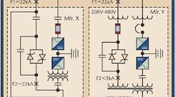
The differences between one manufacturer's designs of the bypass circuit over another can result in a wide disparity in their short-circuit current ratings. To illustrate this point, let's examine units from two hypothetical UPS vendors (see the Figure above). The bypass equipment of Manufacturer X's unit consists of an input contactor, a solid-state switch shunted by a second contactor, and a manual wraparound mechanical switch. Manufacturer Y's unit consists of an input transformer, a current-limiting fuse, a solid-state switch shunted by a contactor, and an output transformer. The Table below summarizes the data for these two units.
To arrive at proper fault current values, you need data on transformer kVA and percent impedance. As part of your evaluation, you need to know a few things about your circuit protection and switches, as follows:
Fuses and circuit breakers:
-
Let-through curves for current-limiting devices.
-
Interrupting rating in rms SYM amps.
Solid-state switches:
-
Short-circuit current rating in rms SYM amps.
-
Withstand rating, I2t in amp2 sec (if rms SYM amps aren't given).
-
Assume 10 times SCR rating if no data is available.
You must base the short-circuit rating of the bypass circuit on the component with the lowest rating — or the manufacturer's specified rating — and the large fault current of the alternate source. Let's assume 22,000A rms SYM fault level (designated as F1) at the UPS input. For Manufacturer X, the fault let-through current of the bypass source must not exceed 2,191A rms SYM at 208V on the load side of the static switch. A fault (F2) on the load side of this switch will subject the device to 10 times the short circuit current it can safely handle. For Manufacturer Y, the fault let-through current of the bypass source must not exceed 2,898A rms SYM at 480V on the load side of the static switch. Manufacturer Y mitigated the fault level by introducing an input transformer and current limiting fuses, which reduced the fault current below 2,898A. Therefore Manufacturer Y is good for connection to a supply with an available fault of at least 22,000A while Manufacturer X is suitable for only 2,191A — a ratio of 10:1.
For Manufacturer X, you would need to externally address short-circuit current reduction. The problem of reducing the fault current to an acceptable value to meet the requirements of 110.10, coupled with the goal of complete coordination among circuit protection devices that support mission-critical systems, is the challenge the power systems engineer must overcome to safely power up Manufacturer X's UPS.
A UPS isn't a black box that solves all power problems, but by obtaining the correct data and doing the math, you can design a reliable power system.
Villarin is president of NV Enterprises Inc., Reston, Va.


