In a perfect world, all the electrical current sent along a conductive wire would reach its intended destination. However, in the real world some of it is lost along the way for various reasons. Wires are insulated with a resistant sheathing to contain the conductivity of the typically copper or aluminum core, but even with this insulation in place, some of the current still manages to escape.
Much like a leak in a water pipe, an imperfection in the insulation of a wire allows a steady flow of electricity to escape, which can be detrimental to electrical circuits and machinery. However, testing can help you determine whether the insulation is performing at an effective and safe level. Routine testing can identify problems before they result in injury or equipment failure.
Insulation is subject to many elements that can cause it to perform at a less-than-acceptable level. Excessive heat or cold, moisture, vibration, dirt, oil, and corrosive vapors can all contribute to deterioration. For this reason, routine insulation testing is necessary.
Total current in insulation testing.
Testing the integrity of insulation requires measuring its resistance to current flow across it. A high level of resistance means that very little current is escaping through the insulation. Conversely, a low level of resistance indicates a significant amount of current may be leaking through and along the insulation.
By pressurizing a conductor with a given voltage, it's possible to use Ohm's Law (R=V÷I) to apply a numerical value to resistance measurements. Divide the voltage by the current that escapes through the insulation and returns to the meter. This total current that flows through and along the insulation during a test is the result of capacitive current, absorption current, and leakage current.
Capacitive current.
The initial burst of current that occurs when voltage is first applied to a conductor is called capacitive current. Like the first rush of water flowing through a hose, it typically starts out high and then drops quickly once the conductor is fully charged.
Absorption current.
Like capactive current, absorption current also starts out high and then drops. However, it falls at a much slower rate. As the voltage builds up, the absorption level in the insulation decreases. This gradual change reflects the storage of potential energy in and along the insulation. Incidentally, absorption current is an important part of the time resistance method of insulation testing.
Leakage current.
Also commonly referred to as conduction current, the small, steady current present both through and over the insulation is called leakage current. Any increase in leakage current over time is usually an indication of deteriorating insulation. This would be noted on the insulation test meter as a decrease in resistance.
Types of insulation resistance tests.
With an understanding of the definition of insulation resistance and why it's important to measure it, it's possible to examine when and how to test.
When installing new electrical machinery or equipment, testing insulation resistance is important for two reasons. First, it ensures that the insulation is in adequate condition to begin operation. This type of initial test is usually referred to as a proof test. Second, it provides a baseline reading to use as a reference for future testing.
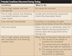
Due to fluctuating factors like moisture and temperature, insulation testing is mostly based on relative measurements. In other words, a reading of 1.5 megohms is more or less insignificant without a previous set of measurements against which to compare it. Measurements taken during routine maintenance tests can give valuable information about the quality of insulation, as conditions vary.
The proof test, short time/spot reading test, time resistance test, and step voltage test are four of the most prominent tests used today, and they encompass the steps necessary for keeping tabs on equipment from installation through day-to-day use.
Proof test
Proof testing is an important step in the installation of new machinery to protect against miswired and defective equipment. A proof test is often referred to as a go/no go test because it tests the system for errors or incorrect installation. The test is accomplished by applying DC voltage through the de-energized circuit using an insulation tester. If no failures occur during the measurement, the test is a success. Proof testing voltages are much higher than those used in routine maintenance test methods. The general guideline for choosing a test voltage is based on the equipment's nameplate rating. Follow the equation below to arrive at an acceptable test voltage.
Step 1: (2×nameplate rating)+1,000V=Factory AC Test
Step 2: 0.8×Factory AC Test×1.6=DC Proof Test Voltage
Short time/spot reading test
In a short time/spot reading test, the tester is connected across the insulation of the motor windings. A test voltage is then applied for a fixed period of time, usually 60 seconds. The most important aspect of this test is that it remains consistent in duration from test to test. Once the time period has elapsed, an insulation resistance measurement can be recorded.
As discussed earlier, a single maintenance test can act only as a rough guide for insulation quality. A more effective use of the short time/spot reading testing method is the establishment of a series of test results over several months so long-term trends may be examined. It's important to understand that a variety of factors like temperature and moisture can cause fluctuations in test readings. Typically, insulation will deteriorate at an extremely gradual, but consistent pace. A significant downward trend over the course of several measurements is usually a sign of insulation breakdown.
Time resistance test.
Unlike the short time/spot reading test, the time resistance method test can provide fairly conclusive results without the luxury of past test measurements. This test method is based on taking successive readings at fixed time intervals, and then plotting the readings. This is an especially effective method when moisture and other contaminants might be present.
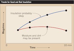
As mentioned earlier, absorption current starts out high and gradually decreases over time as voltage is applied. In a machine with healthy insulation, this trend will continue for several minutes and show an increasing level of resistance. On the other hand, if the insulation is poor, the level of resistance will flatten out after an initial burst (Fig. 1, below).
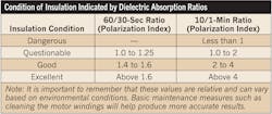
The best way to quantify the results of a time resistance test is through a dielectric absorption ratio. The dielectric absorption ratio consists of two time resistance readings. A commonly used set of intervals is a 60-second reading divided by a 30-second reading. Another frequently used set is a 10-minute reading divided by a 1-minute reading. This resulting value is referred to as the polarization index. The information summarized in Table 1, below, provides general guidelines for interpreting dielectric absorption ratios.
Step voltage test.
A step voltage test involves testing the insulation at two or more voltages and comparing the results. Good insulation will show a relatively consistent resistance reading regardless of the voltage applied. On the other hand, when the resistance level drops as the voltage level increases, it's usually an indication that the insulation is aging, contaminated, or brittle. This occurs because small imperfections like pinholes and cracks reveal themselves under increased electrical stress. When performing a step voltage test, it's important that you start with the lowest test voltage and then move to a higher voltage level. Test duration is typically 60 seconds.
Preparing for the actual test.
Correctly preparing the equipment and insulation tester is crucial to your safety and the well being of your wiring and machinery. Adhere to the following four-step process before every test:
- Take the equipment out of service
Shut down the apparatus, open all switches, and de-energize the unit. Disconnect the equipment under test from all other equipment and circuits, including neutral and protective ground connections. Make sure you follow proper lock-out/tag-out procedures during this step.
- Check what will be included in the test
The more equipment included in a test, the lower the resistance reading. For this reason, it's very important to inspect the installation and understand exactly what you're including in the test. You don't want a true reading to be affected by additional equipment. However, if a complete installation with several pieces of equipment yields a high reading, it's safe to assume that each individual apparatus will yield an even higher reading. Consequently, sometimes separating components is unnecessary.
- Discharge capacitance
It's important to discharge capacitance before and after making an insulation resistance test. You should discharge about four times as long as the test voltage was applied during the test.
- Check current leakage at switches
Make sure readings won't be affected by leakage over and through switches, fuse boxes, or other connections. Such leakage can be detected by watching the level of resistance the moment the test leads are attached. Never perform an insulation test on an energized line or apparatus.
It's extremely important that you consult the motor manufacturer's operating handbook for specific information and guidance as to whether a particular value measured between two points should be considered acceptable or questionable. Insulation testing manufacturers can provide test equipment capable of providing you with accurate readings, but they have no way to determine if a particular measured value indicates that a piece of equipment meets its specifications for insulation integrity.
Gregorec is the test and measurement group manager for Ideal Industries, Inc., Sycamore, Ill.


