Safeguarding your cabling system should be a primary concern.
One of the most important parts of an OSP system, a splice is also one of its weakest links. Locations like tap points, taper points, gauge changes, reel ends, future access points, and cross-connection points need solid protection and a reliable access system, because the splices required at these junctions are subject to environmental degradation, mechanical use and abuse, and physical stresses. With that in mind, manufacturers of these closures take rigid measures to ensure their products will endure normal field situations. But then it's up to you to properly apply these components in the environments for which they were designed.
In this fifth installment of EC&M's 12-part look at the Second Edition of BICSI's Customer-Owned Outside Plant Design Manual, we discuss how cabling hardware (as defined in the ANSI/TIA/EIA-758, Customer-Owned Outside Plant Telecommunications Standard) is used in outside plant (OSP) systems to enclose and protect cable splices. Unlike connecting hardware, which joins the individual conductors or fibers, cabling hardware attaches to the cable sheath.
Splice location is typically the first criterion by which to decide whether your system needs above ground, buried, aerial, or underground cases for use in maintenance holes (MHs) or handholes (HHs), or pole- or wall-mounted closures. When determining your needs, keep in mind that although some splice points may not require re-entry, others may be located in high-activity areas or earmarked for future expansion. You'll need to explore provisions in size, assignments, and built-in expansion features when selecting your products.
Some splice case closure environments, like MHs and HHs, are universal and can accommodate fiber, copper, and coax cable. However, in most cases you'll need to use a different splice closure for each cable type. If you plan ahead, you might be able to co-locate the splices in a universal-type product and reduce the need for multiple closure housings or structures. Many projects may call for just one cable medium, but when you're involved with a project that uses more than one medium, universal-type products are very cost effective.
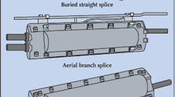
Closures are divided into the following four categories:
-
Straight — only one cable can enter each end of the closure.
-
Branch — two or more cables can enter either end of the closure.
-
Butt — two or more cables can enter only one end of the closure.
-
Universal — adapters are included that allow multiple cables to enter either end of the closure.
Three types of splice closures are shown in the Figure above.
Optical fiber closures.
Optical fiber closures typically hold fibers on a splicing tray that is carefully placed in the closure. These trays must provide adequate strain relief for buffer tubes, pigtails, or pre-terminated modules. Splice trays are available in metallic or plastic versions, for both singlemode and multimode cables. They provide protection for both mechanical and fusion splices. A standard splice tray accommodates a 12-fiber splice capacity for loose-tube or tight-buffered cables. Trays must be large enough to avoid violating the minimum bend radius requirements of optical fiber.
When determining the size and type of closure necessary for an optical fiber system, you must take into account factors such as the number of fibers in the bundle, the mode of the fiber, and whether or not you'll be using mechanical- or fusion-type splices to join the fiber. The organization and labeling of your splices are also critical. Consider not only the immediate needs of a project, but also plan for changes or additions that may occur at a later date. It's necessary to provide additional coiled cable loops for fiber optic splice closures, because they typically aren't re-entered where they are mounted. The photo on page 61 shows a coil example.
Copper closures.
As is the case with optical fiber closures, copper closures store copper splices and protect them from mechanical and environmental damage. Copper closures can be found in aerial, direct-buried, underground, and in-building applications. The size of the closure is based on the number of cable pairs, or splices, you're working with.
Aerial splice closures for copper cable systems are either strand- or pole-mounted. Not only do they protect the cable splices from the environment, but they also bond and ground the cable. They can even be equipped with terminal blocks and fusible-link stub cables to allow for the termination of service wires, reducing the need for two separate products. In rare instances, some existing aerial cables may be pressurized and require the use of a special pressurized closure.
Encapsulated-type closures are effective for direct-buried applications. The cases are available in wraparound heat-shrink and solid-preformed styles. Both have proven reliability and re-entry capability. In the event that these installations may need to be re-entered, you should be very selective when choosing their location.
In some applications, the copper cable in an underground system may be installed under air pressure. In these situations, you must install a special pressurized splice case. However, most new underground systems are designed with non-pressurized cables.
Pedestals can also be used as a means of enclosing spliced copper cable. The connectors used in this application serve as the primary protection for the copper wire.
The protection of your OSP system should be of primary concern in the system design. And nowhere is protection more important than at splice points. Choosing the right closure can mean the difference between a properly running system and unacceptable levels of downtime. Be sure you know what you need before you dig the trenches.
Next month, we'll take a look at the grounding, bonding, and electrical protection requirements of CO-OSP systems.
Hite is special projects engineer-OSP for CT Communications, Inc., Concord, N.C.
The material for this article was excerpted with permission from BICSI's Customer-Owned Outside Plant Design Manual, Second Edition.


