Motor Selection for Adjustable-Speed Drives
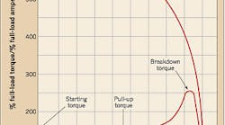
Prior to the advent of the adjustable-speed drive (ASD), the polyphase induction motor operated as a constant-speed motor. Figure 1 shows the well-known torque and current curves versus speed for the motor, where the operating speed is close to 1,800 revolutions per minute. By comparison, Fig. 2 (click here to see Fig. 2) shows the torque-speed curves for a polyphase induction motor operated in an ASD over the frequency and speed range of 10% to 160% of base frequency and speed. In addition to being supplied with voltage and current with a sinusoidal waveform, the induction motor in the ASD can also be supplied with waveforms such as those shown in Fig. 3 on page 22, as generated by the inverter of the ASD.
All of these new waveform and speed options opened the door to potential misapplication by the installer and end-user. This, in turn, brought about the need for a set of guidelines to help them specify the requirements for a polyphase induction motor used in a variable-speed application. A technical paper published in the Nov./Dec. 1991 issue of IEEE Industry Applications magazine by R.H. Daugherty and C.H. Wennerstrom, “Need for Industry Standards for AC Induction Motors Intended for Use with Adjustable-Frequency Controllers,” helped set the stage for development of NEMA Standards Publication MGI-2006, “Motor and Generator, Part 31 Definite-Purpose Inverter-Fed Polyphase Motors.”
Ratings
The basis for the rating curve in Part 31 is shown in Fig. 4. The curve and the numbered points in this figure are explained as follows:
(1) to (4) — Speed range of the motor. Point (1) can be zero speed.
(3) — Base rating point for 100% base speed and voltage.
(2) to (3) — Constant torque range. Inverter provides constant volts per Hertz to ensure a constant level of motor air-gap magnetic field.
(1) — Torque at minimum speed, based on temperature consideration and voltage boost from (2) to (1) to compensate for stator winding IR drop.
(3) to (4) — Constant horsepower range, constant voltage.
(4) — Maximum operating speed.
Limitations
The following limitations apply to the use of an induction motor in an ASD application, as compared to conventional operation of the motor at line voltage.
Duty — Under variable-speed use, the motor is intended for varied operation over the defined speed range. Under continuous use, the motor can be operated at any single speed in the defined range.
Temperature rise — the insulation class and the method of temperature measurements determine the maximum temperature rise of the motor. For variable-speed duty, an equivalent temperature is devised that has the same relative thermal expectancy as for continuous duty.
Speed — The maximum speed, (point (4) in Fig. 4), of the motor has two limitations. First, the continuous speed capabilities as set by the standard (Part 31, Table 12-5). Examples for 1,800 revolutions per minute TEFC motors include: 2,600 revolutions per minute up to 5hp; 2,700 revolutions per minute up to 30hp; 2,300 revolutions per minute up to 2,500hp; and 1,800 revolutions per minute up to 500hp. The second limitation is an emergency over speed in the range of 15% to 25% for 2 minutes.
Voltage — The applied fundamental voltage shall not vary more than +/- 10% from rated. Stator winding insulation systems shall be designed to withstand the following:
-
V rated less than or equal to 600V, V peak = 3.1 × V rated, rise time greater than or equal to 0.1 microseconds
-
V rated greater than 600V, V peak = 2.04 × V rated, rise time greater than or equal to one microsecond
Torque — Figure 4 shows the torque-speed curve for rating purposes. Figure 5 shows the torque capability for a TEFC induction motor versus speed. As the speed is reduced from rated, the fan provides less coolant; the current and torque must be reduced to meet limits of temperature rise. Other issues to consider include bearings, noise, vibration, and name plate rating.
The polyphase induction motor designed for inverter duty can operate over a wide speed range in an ASD. Therefore, it's important that end-users and manufacturers come together on the same page to specify the motor that will operate best in the application required. This is where Standard MGI-2006 Part 31 comes into play and provides the requirements for the motor under all operating conditions.
Kusko is vice president and principal of Exponent Failure Analysis Associates in Natick, Mass. Ayoub is a lead power system engineer with GE Energy in Hanover, Md.


