Inductance is the link between electric circuits and magnetic fields.
Voltage and current sine waves are in-phase when they peak and cross the zero axis at the same time. However, this rarely happens and only in alternating current (AC) circuits containing pure resistances. Most AC circuits contain some type of inductance, in which case the current waveform lags the voltage or reaches its peak slightly after the voltage waveform. A lagging current indicates an inductive circuit.
Sources of inductance. An inductor consists of a coil of wire wound around an iron or non-magnetic (air) core. Current passing through the inductor establishes a magnetic flux. The resulting magnetic field can store energy that is transferred back and forth between the electric circuit and the magnetic circuit produced by the inductor. The amount of inductance is measured in Henrys, the amount of magnetic flux produced by each ampere of current. Inductive reactance is the inductance multiplied by the radian frequency of the system.
Many AC devices contain coils of wire. Transformers, for example, are two or more coils of insulated wire wrapped around an iron core. Motors typically have a stator, a fixed coil of insulated wire that surrounds a second coil of insulated wire, which is free to rotate (the rotor). Transformers and motors are used extensively on most power systems, which makes most AC power systems inductive in nature.
The basics of inductance.
The current flowing through the coiled wire of an inductor produces a magnetic field that circles the conductor. The direction of the magnetic field is found using the right-hand rule. Point the thumb of your right hand in the direction of the current flow. The fingers curl in the direction of the magnetic field.
An alternating current flowing through an inductor produces a time-varying magnetic field. As the field increases in magnitude, it stores energy provided by the electric circuit. As the field collapses, its energy is returned to the electric circuit. This increase/collapse cycle happens 120 times per sec on a 60-Hz system.
Application of inductance.
Inductors, often called reactors in power applications, are used to change the performance of the power system. When connected in series, reactors greatly increase the impedance seen by out-of-phase current. Since the current that flows during a fault is almost 90∞ out of phase with the system voltage, series reactors can be used to limit short circuit current. Current-limiting reactors can provide a cost-effective alternative to replacing circuit breakers when fault current magnitudes exceed equipment ratings. Connecting reactors from line to neutral (in shunt) counteracts the capacitive effects of line charging, which can cause unacceptably-high voltages on very long transmission lines. Shunt reactors are common on extra-high voltage (EHV) lines with lengths in the hundreds of miles.
Effects of inductance.
As the amount of inductance in an AC circuit increases, so will the amount by which the current lags the voltage. The amount of lag is measured in electrical degrees. The cosine of the number of degrees of lag is called the power factor (PF) of the circuit. A purely resistive circuit has no lag (0°). The cosine of 0° is 1, or unity. A unity PF is what you want to achieve in power circuits.
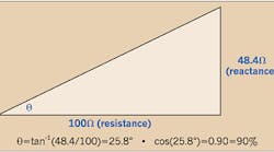
Inductive current is 90° out-of-phase from resistive current. A right triangle, called an impedance triangle, can be formed by drawing a hypotenuse between the resistance and inductive reactive magnitudes. If the inductive reactance in a circuit is 48.4% of the resistance, trigonometry can be used to illustrate that the current will lag the voltage by 25.8°. The cosine of 25.8° is 0.90, or 90%, so the circuit has a 90% lagging PF (Figure above).
We'll later discuss how to bring a 90% lagging PF circuit closer to unity. Good PF is important for the proper operation of a power system. When PF is too low, an electrical system can suffer from poor voltage regulation and excessive losses.
Fehr is an engineering consultant based in Clearwater, Fla.


