Dissolved Gases Reveal Your Transformer’s State of Health
Effective transformer maintenance depends on dissolved gas analysis.
Effective maintenance of liquid-filled transformers begins with prevention of failure by testing transformer oil for unusual elements. The presence of certain gases often indicates an abnormality that could lead to failure if ignored, and advances in gas analysis are making the detection of future transformer problems an increasingly reliable procedure.Dissolved gas analysis (DGA) was born of common dielectric coolant sampling procedures regularly performed by technicians. Fluid samples can reveal the relative value of key performance properties such as water content and dielectric strength, and key relative characteristic indicators such as color, dissipation factor, interfacial tension, and neutralization number. You can use DGA to optimize the loading cycle of the transformer, helping you achieve the maximum return on your investment. It also allows the earliest warning of excess stress within the unit, well before an unplanned outage occurs. The usefulness of DGA is increasing rapidly, but this important diagnostic tool is available only for liquid-filled transformers.
When performing DGA, it is important to differentiate between combustible gases and non-combustible gases. Though significant amounts of non-combustible gases and the problems they create are common in transformers when fluids are exposed to air in the headspace in the tank, they do not pose a safety hazard. On the other hand, large quantities of combustible gases in transformer fluid and the headspace above the fluid could cause fire and explosion. In most cases, combustible gases, or “fault gases,” occur in very small quantities when oil or paper insulation breaks down. However, when thermal and electrical stresses exceed the design or operational limits, fault gases can form in significant volumes. The type and severity of the abnormal condition have the greatest impact on what kind of fault gases form and how quickly they accumulate.
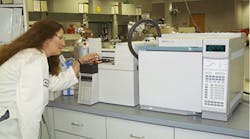
The flammability of headspace gases makes it important to follow precautions when extracting, storing, transporting, and testing fluid samples. Although it’s possible to test samples on your own (portable combustible gas detectors are available for field use), the dangers the procedure presents make it a risky proposition. Sending samples to qualified material testing laboratories is the safest option (Photo 1). Transformer design, manufacturing, and operational variables will affect acceptable gas levels, generation rates, concentrations, and the time it takes for the gases to distribute evenly throughout the unit. Once the lab determines the types of gases and their quantities, the next (and perhaps most difficult) step is determining whether their concentration is high enough to cause significant problems.
In addition to the physical characteristics of the transformer, the sampling location and technique, type of dielectric coolant, test method, and data analysis method are important to keep in mind when considering an analysis. For example, the presence of even a trace amount of acetylene could be a problem for bolted cover designs, but it wouldn’t be cause for concern in welded cover transformer designs. It’s also common practice to look at the trend of the dissolved gas content of samples taken from one transformer over a period time. This will make it more apparent which variables are affecting the DGA levels and help prevent a misdiagnosis.
Soon, it may not even be necessary to take samples manually. Manufacturers are beginning to design large power transformers with built-in combustible gas detectors and relay devices, which trigger a relay or alarm when gases exceed acceptable levels. Although expensive, the devices continuously monitor for gases in the oil or headspace, and some record gas levels daily, for trend analysis.
Let’s look at a case history where a $90 battery of routine DGA tests saved a grain terminal over $50,000.
Near the Twin Cities, a mammoth grain elevator operation for storing grain and loading it into barges on the Mississippi River uses a 2,500 kVA roof-mounted transformer. Dynex Corp., a third-party maintenance contractor based in St. Paul, Minn., does DGA testing as part of its maintenance plan. The company’s DGA analysis revealed the combustible gas level results exceeded the recommended value of the IEEE C57.104 guide. Subsequent samples indicated a slow, but steady additional buildup of gas levels. By applying the diagnostic methods known as Rogers Ratios and Dornenberg Ratios, Dynex determined that a fault condition of high temperature arcing in a small confined area was likely. That area could have included a poor primary connection, a bushing with a defect in the section submerged in the fluid, or a turn-to-turn short in the primary winding. Because of the high level of dissolved gases, it was likely the headspace between the coolant level and the tank cover would also contain significant levels of combustible gases.
This unit is expensive to repair. To get it to the repair shop, Dynex would’ve had to vent, purge, and drain the unit so a helicopter could safely remove it from the rooftop. The DGA analysis not only prevented catastrophic damage, but it allowed the repair shop to save significant time—meaning an earlier return to service. The repair shop traced the source of the fault gases to an improper crimp connection on a primary lead between an HV bushing and an accessory. After making repairs, they returned the unit to service, and it has been working perfectly ever since.
Catching small problems before they become big is critical to keeping your transformers operational, and dissolved gas analysis is an increasingly viable option for preventing failure in liquid-cooled transformers. Although advances in preventative maintenance have yet to yield a technique as reliable for dry-type transformers, DGA is making transformer maintenance easier and more effective at uncovering potential failure.
McShane is an engineer with Cooper Power Systems, Milwaukee.
Photo Courtesy of the Thomas A. Edison Technical Center - Cooper Power Systems - Franksville, WI


