Whether they're for journeymen, master electricians, or contractors, most electrical licensing exams require you to calculate residential loads and service or feeders sizes using one of two methods. The standard method, which is contained in Art. 220, Part II, involves more steps, but many people use it exclusively to avoid using the wrong method. However, most residential construction qualifies for the optional method in Art. 220, Part III, so it's prudent to understand both methods. In either case, you're free to exceed the NEC requirements — these are minimum requirements, not design specifications.
The standard method is where we'll start. It requires six sets of calculations for general lighting and receptacles, small-appliance, and laundry; air conditioning versus heat; appliances; clothes dryer; cooking equipment; and conductor size.
The following example should help illustrate how to apply these steps.
What size service conductor does a 1,500 sq ft dwelling unit need, if it contains the following loads? The service is 120/240V.
-
Disposal (940VA)
-
Dishwasher (1,250VA)
-
Trash compactor (1,100VA)
-
Water heater (4,500VA)
-
Dryer (4,000VA)
-
Cooktop (6,000VA)
-
Two ovens (each 3,000VA)
-
Air conditioning (5 hp, 230V)
-
Three electric space heating units (each 3,000W)
General lighting and receptacles, small-appliance, and laundry. The NEC recognizes these circuits won't all be on (loaded) simultaneously. Thus, you may apply a demand factor to the total connected general lighting and receptacle load (220.16). To determine the service/feeder demand load, refer to Table 220.11 and follow these steps:
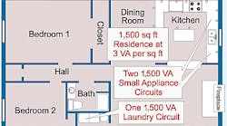
First, determine the total connected load for general lighting and receptacles (3VA per sq ft) [Table 220.3(A)], two small-appliance circuits each at 1,500VA, and one laundry circuit at 1,500VA (220.16) (Fig. 1).
Second, apply Table 220.11 demand factors to the total connected general lighting and receptacle load. Calculate the first 3,000VA at 100% demand and the remaining VA at 35% demand.
General lighting/receptacles: 1,500 sq ft× 3VA=4,500VA
Small-appliance circuits: 1,500VA×2 =3,000VA
Laundry circuit: 1,500VA×1= 1,500VA
Total connected load: 4,500VA+ 3,000VA+1,500VA=9,000VA
First 3,000VA at 100%=3,000VA× 1.00=3,000VA
Remainder at 35%=(9,000VA- 3,000VA)×0.35=2,100VA
Total demand load=5,100VA
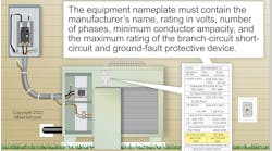
Air-conditioning versus heat. Because air-conditioning and heating loads aren't on simultaneously, you may omit the smaller of the two loads (220.21). Calculate each of these at 100% (220.15) (Fig. 2).
Air conditioning: 5 hp, 230V
VA=E×I (Table 430.148)
28 FL×230V=6,440 VA
Heat: 3,000W×3 units=9,000W
The air conditioning load is smaller than the heat load, therefore it can be omitted.
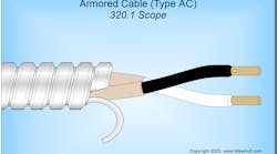
Appliances. Per 220.17, you can use a 75% demand factor when four or more “fastened in place” appliances, such as a dishwasher or waste disposal, are on the same feeder. Don't include clothes dryers, cooking equipment, air conditioning, or heat in this category (Fig. 3).
Waste disposal: 940VA
Dishwasher: 1,250VA
Trash compactor: 1,100VA
Water heater: 4,500VA
Total connected appliance load: 7,790VA× 0.75=5,843VA
Clothes dryer. Per 220.18, the feeder or service demand load for electric clothes dryers in a dwelling unit shall not be less than 5,000W. However, if the nameplate rating exceeds 5,000W, use that rating as the load. You can omit this calculation if the unit has no electric dryer provision. However, it's common to provide both gas and electric sources. If you see gas on the plans, verify electric will be omitted (Fig. 4).
The service and feeder demand load for a 4kW dryer is 5,000W.
Cooking equipment. For household-cooking appliances rated higher than 1.75kW, you can use the demand factors listed in 220.19, Table and Notes 1, 2, and 3.
All three of the units in the example are rated higher than 1.75kW and not higher than 8.75kW, so follow the instructions in Note 3. The two ovens are rated less than 3.5kW, so Table 220.19 Column A demand factor applies. The cooktop is 6kW, so Column B demand factor applies (Fig. 5).
Column A demand: 3kW×2 units× 0.75 demand factor=4.5kW
Column B demand: 6kW×1 unit× 0.8=4.8kW
Demand load=4.5kW+4.8kW= 9.3kW=9,300W
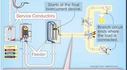
Feeder and service conductor size. 400A and less: For 3-wire, 120/240V, single-phase systems, size the feeder or service conductors according to Table 310.15(B)(6). For all others, use Table 310.16. Size the grounded (neutral) conductor to the maximum unbalanced load (220.22) per Table 310.16.
Over 400A: Size the ungrounded and grounded (neutral) conductors per Table 310.16.
Now we can total up the demand loads from steps 1 through 5.
Step 1: 5,100VA
Step 2: 9,000VA
Step 3: 5,843VA
Step 4: 5,000VA
Step 5: 9,300W
Step 6: 34,243VA total demand load To determine the amperes need for the service use the formula: I5VA÷E.
I=34,243VA÷240V=143A
We can use 310.15(B)(6) for a 120/240V single-phase dwelling service and feeder up to 400A. This Table allows a smaller conductor size than Table 310.16.
A 143A demand load means this house requires at least a 150A service with 1 AWG conductors.
Optional method. You can use the easier optional method found in 220.30 only when the total connected load is served by a single 3-wire, 120/240V or 208Y/120V set of service or feeder conductors with an ampacity of 100A or greater. Because this condition describes the typical residential service, the optional method is likely to apply. Using it can simplify the design process and save you time because you have so many fewer sets of calculations.
General loads. The calculated load shall not be less than 100% for the first 10kW, plus 40% of the remainder of the following loads:
-
Small-appliance and laundry branch circuits: 1,500VA for each 20A circuit.
-
General lighting and receptacles: 3VA per sq ft
-
Appliances: The nameplate VA rating of all appliances and motors fastened in place (permanently connected) or on a specific circuit. Be sure to use the range and dryer at nameplate rating.
HVAC. Include the largest of the following:
-
100% of the nameplate rating of the air-conditioning equipment.
-
100% of the heat-pump compressors and supplemental heating, unless the controller prevents simultaneous operation of the compressor and supplemental heating.
-
100% of the nameplate ratings of electric thermal storage and other heating systems where you expect the usual load to be continuous at the full nameplate value. Don't configure such systems under any other selection in this table.
-
65% of the nameplate rating(s) of the central electric space heating, including integral supplemental heating in heat pumps where the controller prevents simultaneous operation of the compressor and supplemental heating.
-
65% of the nameplate rating(s) of electric space heating, if there are less than four separately controlled units.
-
40% of the nameplate rating(s) of electric space heating of four or more separately controlled units.
Sizing service/feeder conductors. Now that we've seen how to determine residential loads, let's size the service/feeder conductors. We'll use the same specifications that we used for the standard method so we can compare apples to apples.
Step 1: Determine general loads [230.30(B)].
Small appliance: 1,500VA×2 circuits = 3,000VA
General lighting: 1,500 sq ft×3VA= 4,500VA
Laundry circuit=1,500VA
Now add up the appliance ratings.
- Disposal (940VA)
- Dishwasher (1,250VA)
- Trash compactor (1,100VA)
- Water heater (4,500VA)
- Dryer (4,000VA)
- Ovens (3,000VA×2 units=6,000VA)
- Cooktop (6,000VA)
The total connected load=32,790VA
Calculate the first 10,000VA at 100%=10,000VA× 1.00=10,000VA
Calculate the remainder at 40%= 22,790VA×0.40= 9,116VA
Demand load=10,000VA+9,116VA= 19,116VA
Step 2: Compare air conditioner at 100% vs. heat at 65% [220.30(C)].
Air conditioner: 230V×28A=6,440VA
Heat [220.30(C)(5)]: 9,000 W×0.65 = 5,850 W (omit)
Step 3: Calculate service/feeder conductors per 310.15(B)(6).
General loads=19,116VA
Air conditioning=6,440VA
Total demand load=25,556VA
I=VA÷E=25,556VA ÷ 240V = 106.5A
310.15(B)(6) requires at least a 110A service with 3 AWG conductors.
As you can see, in this case the optional method permitted a smaller service than the standard method of calculating a service for a dwelling.
Now that we've walked through the process of calculating residential services and feeders, you can see that doing so is fairly easy. You need to calculate the loads first, and then move on to the service and feeder size. The NEC provides the requirements in Art. 220 and 230. Doing these calculations correctly can save you money during design and construction, while providing safe homes for the families who occupy them.


