Obtaining reliable data from electric utilities about magnitude and duration of single-phase, line-to-ground fault currents at the service entrance of commercial and industrial facilities is of critical importance in the design of an end-user substation grounding grid. In ground-fault conditions involving the primary side of a substation, circulation of current through the grounding grid will occur, and touch and step potentials will be present at the end-user’s premises. Ground faults occurring immediately outside of the zone of protection of the end-user’s most upstream protective device — at the service entrance of the facility — may only be cleared by the electric utility’s protective device. In this case, the duration of the ground-fault current, as well as its magnitude, depends on the electric utility network and its protection system. An electrical designer must request this data so he or she can properly size the grounding grid and assess the safety of the service entrance substation. The adoption of a standard form, containing the necessary basic input data to be sent to utilities during the design phase, would greatly simplify the process.
Grounding system basics
The grounding systems of substations have a paramount protective function when a ground fault occurs on the primary side of the transformer. The grounding grid must be able to contain touch and step potentials within their permissible values as well as safely dissipate the excess current. In the case of failure of the basic insulation of equipment supplied through the secondary winding of the substation transformer, the fault current goes back to the source through equipment grounding conductors, and the actual earth forms no part of this fault-loop.
It is important to note that a grounding system does not automatically guarantee the safety of the installation — all parameters being equal, its effectiveness depends on the magnitude and duration of ground-fault currents. Longer fault durations for low-magnitude touch voltages may be lethal too.
Magnitude and duration of ground-fault currents, therefore, must be analyzed when designing ground electrodes so that the maximum allowable value of the ground resistance of the grid that guarantees safe values of ground potential rise (as well as of touch and step voltages) can be determined.
Touch and step potentials
Effective touch (UvT) and step (UvS) potentials are defined as potentials caused by faults, which energize the grounding system and expose persons to the risk of electric shock due to potential differences across:
• the hand(s) of the person touching the faulted grounded enclosures, and his/her feet;
• both feet of the person standing in the area of influence of the grounding system.
The prospective touch voltage (UT) is instead defined as the potential difference between the ground electrode, or metal parts connected to it, and the earth occupied by the person at a distance of 1 meter, when the ground electrode, or metal parts, are not being touched by the person. (Note: 1 meter is conventionally considered the distance equal to a person’s normal horizontal reach as well as the distance between feet.) It is important to note that the value of the effective touch voltage differs from the value of the prospective touch voltage due to the person’s body impedance.
Ground-fault currents
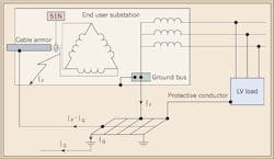
As noted earlier, ground faults occurring on the primary side of a substation will cause current to circulate through the substation ground grid and the actual soil (Fig. 1). However, the fault current (IF) may return to the high-voltage source through additional metallic paths (e.g., overhead ground wires of transmission lines or the metal sheath and armor of cables). In these cases, a considerable portion of the fault current can be diverted away from the ground, and both ground potential rise and potential gradients in the substation area will be lessened, with evident benefits for the safety of the personnel.
If both the high- and low-voltage systems in the facility share the same grounding grid (as they generally do), the circulation of the earth current (IG) also causes energization of all the bonded enclosures, which are connected for safety via the equipment grounding conductor. Persons are, therefore, exposed to touch voltages — and, due to the circulation of fault currents through the earth, to step voltages.
Location of the ground fault
The primary ground fault might occur outside of the zone of protection of the most upstream end-user protective device (e.g., see 51N in Fig. 1 on page 28), but still within the service entrance of the facility.
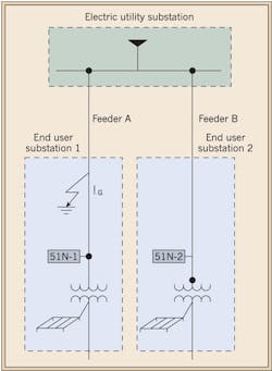
Electric utilities may require that such zone of protection should be limited so as not to comprise the upstream area, which might include the incoming cables. The concern is the end-user’s protective device might trip upon ground faults involving the supply feeders. The reason for this restriction is exemplified in Fig. 2.
A ground fault occurring along the electric utility Feeder A (which supplies End-User 1) should not trip the protective device 51N-2 of End-User 2; this might happen if the zone of protection of 51N-2 included the upstream network. In this case, the continuity of service to multiple users would be compromised because of a single fault.
To prevent the loss of multiple services, electric utilities selectively clear the ground fault by isolating the faulty line. The downside aspect of this solution to the end-user is that both magnitude and duration of touch and step voltages are variables not under the user’s control. Therefore, it is clear that electric utilities should provide single-phase, line-to-ground fault current (If) and fault duration (tf) values to electrical designers to allow the minimization of touch and step potentials through the proper design of the substation ground grid.
Safety criteria
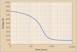
The hazard to persons in contact with an energized object is caused by the circulation of sufficient current to trigger ventricular fibrillation. This asynchronous status of the heart, although reversible, can only be overturned with the use of defibrillators. The body current limits, for power-frequency purposes, are generally translated into voltage limits (UTp) as a function of time so that a comparison with the calculated touch voltages can be performed (Fig. 3).
The curve of Fig. 3 for the current path hand-to-foot is based on data included in IEC/TS 60479-1:2005, namely for a person’s body impedance not exceeded by 50% of the population, a permissible body current corresponding to the curve c2 included in the TS 60479-1 (which describes a probability of ventricular fibrillation less than 5%), and a heart-current factor (F) chosen according to Table 12 of the TS 60479-1.
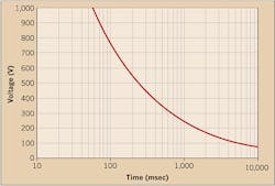
An alternative to the IEC curve of Fig. 3, the IEEE 80 curve of Fig. 4 can be used. The IEEE 80 touch voltage curve is based on a soil resistivity of 100Ωm and a gravel surface of 0.1m with a resistivity of 1,000Ωm; it is also assumed a person with a body mass of 50 kg.
The IEC 61936-1 standard states that, as a general rule, satisfying the touch voltage requirements also satisfies the step voltage requirements; this is because the tolerable step voltage limits are much higher than touch voltage limits due to the different current path through the body, which hardly involves the heart. As a consequence, the step voltage magnitude is no longer employed as a criterion to size grounding grids according to IEC standards.
It’s interesting to note that standard EN 50522:2010 specifically introduces the value of 1kΩ to represent an average magnitude of resistance for old and wet shoes to be considered in series with body resistance. The standard also states that higher values of footwear resistance may be used where appropriate.
To complete a proper ground grid design, you should follow these recommended steps:
1. Collect data from electric utility (i.e., single-phase, line-to-ground fault current, and fault duration) and layout of equipment.
2. Base the initial design of the grounding grid on the functional requirements of the substation.
3. Measure soil characteristics (i.e., soil resistivity of layers).
4. Determine the current (IG) discharged into the soil from the grounding grid, based on the single-phase, line-to-ground fault current communicated by the electric utility, taking into account current splits, worst-case fault, and future expansions.
5. Determine the overall impedance-to-ground of the grid (RG,) based on the layout and soil characteristics.
6. Determine the ground potential rise (UG = RG x IG).
7. Determine permissible touch voltage based on clearing time (tf) communicated by the electric utility (Fig. 3 or 4).
8. If UG ≤ UTp and UG ≤ 1,200V (if tf ≤ 0.5 sec) or UG ≤ 250V (if tf ≥ 0.5 sec), the design is complete.
9. If not, measure/determine if touch voltages inside and in the vicinity of the grounding system are below the tolerable limits (Fig. 3 or 4); if the touch voltages are below the tolerable limits, the design is complete.
10. If not, improvement of design is required; repeat above steps.
It appears clear that if the electric utility does not provide (If) and (tf) during the design phase of the project, the engineer doesn’t have a rational criterion to optimize the design of the grounding grid by properly lowering the RG value. This may compromise the electrical safety within the facility in the case of ground faults.
In conclusion
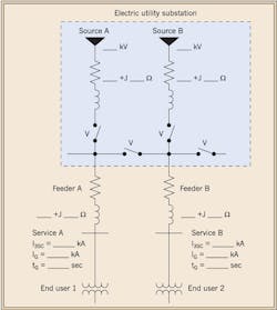
It has been substantiated that initial and complete input data from electric utilities is crucial at the beginning of the design in order to obtain an accurate model of the substation ground grid and, therefore, guarantee the electrical safety of the facility. However, communications from the electric utility may not be standardized, and may vary from one department to another within the same organization. This is why it’s crucial that the electric utility should — at the very least — communicate the following parameters:
• Magnitude of 3-phase, short-circuit currents (i.e., I3sc) and/or the Thevenin equivalent impedance at a given voltage of the source;
• Impedance of feeder(s);
• Magnitude and duration of single-phase line-to-ground fault currents (i.e., If and tf) at the service entrance.
Figure 5 shows a sample form that could be sent to the local electric utility at the beginning of the design phase of the project. You can ask the electric utility engineer to fill in the blanks, close/open the “virtual” switches (V), and add/remove feeders, according to the actual arrangement of its substation and the contractual agreement with the end-user (customer). This type of form would provide (in a non-ambiguous fashion) the basic information necessary to properly model and design the end-user substation ground grid.
Mitolo is a senior consultant with ESI – Engineering & Scientific Investigation, Foothill Ranch, Calif. He can be reached at [email protected].
