This story begins with a puzzling situation for building engineers at The Ritz Plaza in New York City. The two-year-old cold cathode cove light sitting above the indoor swimming pool saw its transformer burn up for a second time in 22 months. The first time the transformer failed, the manufacturer replaced it because it was still under warranty. But after the repeat failure, the building owner (Stonehenge Management) wanted answers before agreeing to shell out $10,000 for the new unit.
Was this failure caused by an electrician’s improper wiring job? Could it have been a defect of cold cathode equipment? Was moisture from the pool creating a problem? Was an engineering design error to blame? With some early cold cathode lighting design experience at Columbia University Student Center under my belt, I was brought in to investigate the situation and get the owner some answers.
As it turns out, the high-rise residential tower has a gym on the third floor. To maintain adequate voltage levels for the upper floors, the electric utility’s service was set at an upper limit of 220V instead of nominal 208V. As voltage fluctuated, the cathode transformer was seeing voltage between 121V and 133V single phase — or 210V to 230V three phase. Keep in mind a cold cathode lighting system works well at a slightly lower voltage than 120V, but not at higher voltage levels. This meant the occasional upper voltage reading of 133V ended up destroying the transformer. I reasoned if we could reduce the voltage by 8V — and limit the transformer operating voltage to 125V — this problem would go away.
As most electrical engineers and electricians know, an electrical system has voltage drop due to resistance of cables (e.g., the longer the cable, the bigger the voltage drop). When voltage drop becomes an issue, electrical engineers and electricians typically solve the problem by increasing cable size or even running paralleling sets of conductors to reduce resistance between the source and the load. At the Ritz Plaza swimming pool, however, the opposite problem existed. Although a rare case, I planned to insert a resistor into the lighting circuit to reduce the voltage level seen by the transformer.
Ohm’s law states that the current through a conductor between two points is directly proportional to the potential difference across the two points. Introducing the constant of proportionality (i.e., the resistance), we arrive at the usual mathematical equation that describes this relationship.
I = V/R or V = IR or R = V/I
Where I is the current through the conductor in units of amperes, V is the potential difference, commonly known as voltage (measured across the conductor in units of volts), and R is the resistance of the conductor (or electrical load such as a lamp) in units of ohms. More specifically, Ohm’s law states that the R in this relation is constant, independent of the current.
But this story can’t be told without the introduction of one more piece of electrical theory. We must also look at the power or wattage in this circuit arrangement. Its mathematical equation is expressed as W = V × I, where W is the wattage assuming unity power factor.
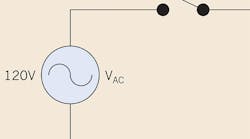
To simplify the situation, I modeled the 1kW cold cathode lighting transformer as a pure resistor (R1) (Fig. 1). Note: 1kW is measured at nominal voltage of 120V.
We use the following formula to find the value of R1:
R1 = V/I = V2/W = 1202/1,000 = 14.4 Ω
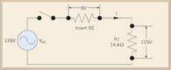
To limit the voltage to 125V across R1 when the supply voltage hit a high of 133V, a new resistor (R2) needed to be inserted in series with R1. The addition of resistor R2 means that an 8V drop would be seen across R2. The remaining voltage (125V) will be seen across resistor R1 (Fig. 2).
We use the following fractional comparison to find the value of R2:
VR2/R2 = VR1/R1
8V/R2 = 125V/14.4
Rearranging the equation to solve for R2 results in R2 = 0.92 Ω.
At this point, I purchased two 0.9 Ω rib-wound resistors for a total of $32. After inserting one of them into the circuit path, the problem was solved at an expense of less than 70W of heat loss due to the resistor. The second backup resistor still sits on my desk to this day, having never been called into service.
This case study is a great example of how sometimes the most simple solution can offset a rather expensive repair bill — and how a basic law of electrical theory can solve real-world problems.
Teng is a registered professional engineer and currently serves as a founding partner at ST Engineering Services (STE) LLP in New York. He can be reached at [email protected].


