Last month, we showed how you could use vector diagrams and simple math to calculate neutral currents in 3-phase, 4-wire circuits. In this last installment, we'll talk about using simple parallelogram relationships and trigonometry to determine neutral currents in balanced and unbalanced circuits.
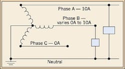
Suppose you have a 3-phase, 4-wire circuit in which there are only two phase-to-neutral loads, as shown in Fig. 1. In addition, one of these loads varies. How can you calculate the neutral current by using vectors?
Because there is no Phase C-to-neutral load, the Phase C current is zero, and the resulting vector diagram will show only phase vectors A and B, 120¡ã apart, as shown in Fig. 2. And because the Phase A-to-neutral load is fixed, we know that the Phase A current is 10A.
As the Phase B-to-neutral load varies, the neutral current also will vary. Let's start with a Phase B current of 10A. We know from Problem 1 of the Part 3 installment in the October 2008 issue that the neutral current also is 10A. This is because the phase vectors A and B are of equal magnitude. By drawing dotted lines parallel and of equal length to these vectors, we create a parallelogram having equal sides. When we draw the neutral vector N, we divide the parallelogram exactly in half and create an equilateral triangle ¡ª one in which all sides are of equal length (magnitude here), and all interior angles are 60¡ã. Therefore, the resultant vector N also will have the same magnitude as phase vectors A and B.
How about when the Phase B current equals zero? Well, in this instance, the system effectively becomes single-phase, and the neutral current is again 10A.
For the Phase B currents between zero and 10A, we can use some trigonometry and equations applicable to parallelograms to calculate the respective neutral currents. First, let's draw a typical parallelogram, as shown in Fig. 3, with sides A and B. To find the length of the diagonal line P, we use the following equation:
P = ¡Ì [ (A2 + B2) - (2AB cos ¦È) ] (Equation1)
Keeping the above equation in mind, let's draw a vector diagram, as shown in Fig. 4, and assume Phase B current is 7.5A. What will the neutral current be?
Using Equation 1, you substitute 10A for ¡°A¡± and 7.5A for ¡°B¡±. We know the angle is 60¡ã, and we determine that cos 60¡ã is .500 from a trigonometric table. The resulting calculation is as follows:
N7.5 = ¡Ì(A2 + B2 -2AB cos ¦È)
= ¡Ì [ (102 + 7.52) - (2 ¡Á 10 ¡Á 7.5 ¡Á .500) ]
= ¡Ì [ (100 + 56.25) - 75 ]
= ¡Ì 81.25 ¡Ö 9A
By substituting differing values for Phase B current in Equation 1, you can obtain the respective neutral currents. For example, if the Phase B current is 5A, the calculation results in a neutral current (N5) of 8.66A. For a Phase B current of 2.5A, the neutral current (N2.5) again will be approximately 9A.


