If you're responsible for maintaining quality power at a commercial facility and you've got a problem with harmonics, your best bet is to install a series of active filters. Opting for such filters keeps you from getting locked into paying for power factor correction — an unnecessary feature in commercial facilities — like you can when using passive filters. Not only that, you don't have to worry that small active filters will overload, unlike their passive counterparts that tend to absorb harmonic currents. That's because active filters only compensate for the load currents they're monitoring. They ignore harmonics from the rest of the facility.
When you're applying active filters, you should look closely at your harmonic control requirements and size the filter to solve the problem — it's not necessary to correct for every amp of harmonic current that comes from the nonlinear loads. This can result in considerable savings in the filter size required.
You should also consider other factors when sizing your active filters, depending upon the harmonic problem you're trying to combat. Overloaded neutral conductors and adjustable speed drives are two of the most prevalent enemies of quality power, but each can be solved with properly sized active filters.
Excessive neutral currents due to power supply loads
Overloaded neutral conductors are probably the most common harmonic problem encountered in commercial facilities. The problem occurs when electronic power supply loads like PCs create third harmonic currents that add in the neutral, or zero sequence. If the entire load on a circuit consisted of this type of load, the rms neutral current could be as high as 173% of the rms phase current. The problem is aggravated because neutral conductors — especially in older buildings — are often sized for less current than the phase currents.
First, this waveform can be used to develop a curve for estimating the neutral current (rms value in percent of the phase current rms value) as a function of what portion of the load on the circuit is electronic load. Notice in Fig. 2 that the neutral current is as high as the phase current when the electronic load reaches about 65% of the load on the 3-phase circuit.
- Compensation for the entire harmonic current in the nonlinear loads.
- Compensation for enough harmonic current so the neutral current is always less than the phase current.
Both curves are given as a function of what portion of the load on the circuit is power supply-type, just like the curve in Fig. 3. Applying the second scenario, we only need an active filter if the electronic load is more than 65% of the load on the circuit. Consider the following example. If you have a 100kVA circuit and the entire load is electronic, you could buy an active filter rated for 170A to cancel all the harmonics from the electronic loads (1.7A/kVA×100kVA). On the other hand, an active filter rated 60A would be sufficient to make sure the neutral current is less than the phase current.
Harmonic distortion caused by adjustable speed drive loads
The other concern common in commercial facilities — as well as many industrial facilities — is the increased harmonic distortion levels created by adjustable speed drives (ASDs). Sometimes large UPS systems can have similar characteristics, but this example will focus on ASDs. Generally, ASDs improve efficiency and result in significant energy savings in HVAC motor applications. However, as these loads become a larger percentage of the total load in facilities, they can result in increased voltage distortion levels. This can be particularly important if these loads have to be supplied by backup generation for some conditions like at a water treatment plant.
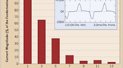
The voltage distortion that results from the ASD harmonic currents is a function of the system impedance and the amount of harmonic current. You can usually prevent problems by making sure the total load for the facility or total load that must be supplied from a backup generator complies with the limits in IEEE 519. For a nonlinear load characteristic like the one in Fig. 4, the most important limit will almost always be the limit for the fifth harmonic. The limit for most realistic short circuit ratios is 8% of the average maximum demand load current. You can use this to determine the penetration level when ASD loads start to be a concern. Fig. 5 shows the total load fifth harmonic current distortion (percentage of total load current) as a function of the amount of ASD load. It shows that you've reached the limit when the ASD load is about 20% of the total load, which isn't a very high penetration level. This illustrates the importance of controlling the harmonics from ASD loads.
- Compensation for the entire harmonic content in the ASD load.
- Compensation for enough harmonic current so the total load current complies with the limits in IEEE 519.
Again, you can save money by sizing the active filter to meet the requirements of the harmonic control, rather than compensating for the total harmonic content. In this case, if the entire load comprises ASDs, the required active filter rating to compensate for all of the harmonics is about 0.5A/kVA of load (480V system). In order to meet IEEE 519 requirements, you can reduce this to 0.4A/kVA of load. For a 500kVA load, you would need 200A of compensation, rather than 250A. The difference is even more dramatic when only a portion of the load consists of adjustable speed drives.
Installing a series of active filters will help you take better control of the power quality needs at your commercial facility. To achieve greater savings, however, remember to size your active filters appropriately.
McGranaghan is vice president of Electrotek Concepts, Nashville, Tenn.


