Both voltage and current divide in these circuits
Electric circuits often consist of several elements, some combined in series and others in parallel. The methods used to analyze series and parallel circuits can be combined to analyze these series-parallel circuits.
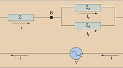
Series-parallel circuit. The Figure at right shows three impedances; two are connected in parallel and then connected in series with a third impedance. Each impedance can be a pure resistance, a pure inductance, a pure capacitance, or any combination of the three.Here current (I) flows from the voltage source (V). The total current flowing from the source flows through impedance Z1 (I = I1). Using node C as a voltage reference, the voltage at node A is the voltage of the source (V). To obtain the voltage at node B, the voltage at node A must be decreased by the voltage drop across the impedance Z1, or VB=VA-(I1×1).
Current division. The elements between nodes B and C are connected in parallel, so it's now necessary to use parallel circuit analysis methods. Both impedance elements (Z 2 and Z 3) have the same voltage across them (V B - V C), but the currents through them (I 2 and I 3) can be different. These currents can be found by applying Ohm's Law:Using these results, you can derive an expression for current division. The voltage difference VB - VC can be expressed using Ohm's Law: VB - VC = I2 ×2 = I3 ×3. Rearranging this equation gives you
Applying Kirchhoff's Current Law at node B yields I1 = I2 + I3, or I2 = I1 - I3. Substituting for I3 gives you
Solving for I1 gives you
Now, resolving for I2 gives you
Similarly, it can be shown that
These equations show how current divides through parallel impedances.
Voltage division. Determining the voltage at node B relative to node C illustrates the concept of voltage division. The paralleled impedances Z 2 and Z 3 can be equivalenced as Z T, whereSolving this equation for ZT gives you
Using node C as the voltage reference, the voltage at node B is the total current (I) times the equivalent impedance ZT. It's been shown that VB = VA - (I1 × Z1). Setting the two expressions for VB equal,
Solving for VA gives you
or VA-C = I1 (Z1 + ZT). You can also express it as VB-C = I1 ZT. You can use these equations to determine the voltage division across two series impedances. Applied to our sample circuit,
Inductance and capacitance. When impedances contain inductance and/or capacitance values, their numeric values are complex numbers that consist of a real component (the resistance) and an imaginary component (the reactance). Mathematically, imaginary numbers contain a factor of sq root -1, denoted by a "j." So a complex impedance consisting of 3 ohms of resistance and 4 ohms of inductive reactance is written as 3 + j4. The presence of the j can lead to arithmetic mistakes if you're not careful. Remember that j×=j2=-1 to avoid errors.


