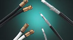
In an effort to support cable television and surveillance video systems, not to mention enable high-speed Internet access, electrical contractors are increasingly installing coaxial cabling in residential and small business installations these days. They're also dabbling in Voice over the Internet Protocol (VoIP) and composite audio and video connections in high-end home theater applications — both of which can also use coaxial cabling.
Selecting the right coaxial cable and properly installing it can be challenging for those not familiar with the many types of constructions and connectors currently on the market. Different cable compositions and performance requirements apply to baseband applications, such as closed circuit television (CCTV) video, and broadband applications, such as cable television (CATV) video. Let's take a look at the most important factors to consider when working with coax.
Types of coaxial cabling. As the name implies, baseband applications operate at very low frequencies. Video surveillance systems typically use RG-59 type coaxial cable equipped with BNC connectors to transport a video image from a surveillance camera to a monitor located in a guard location. The RG-59 cable can be used for distances up to 750 feet. There is also a miniature RG-59 cable construction available, which is good for 375 feet. Because of its smaller size, the miniature RG-59 is frequently installed in areas requiring multiple cameras, such as schools and gaming casinos.
For larger installations, such as parking garages, RG-6 type cable is used because its larger diameter allows for transmission distances of up to 1,500 feet. These CCTV signals require a bare copper center conductor, surrounded by a foamed dielectric insulator, over which a bare copper braid and fire-retardant PVC jacket are applied. The low-frequency signal needs the conductivity of a bare copper conductor and the shielding performance of the bare copper braid to perform well at these low frequencies.
Broadband applications operate at frequencies as high as 3,000 MHz (or 3 GHz). This is 3,000 million cycles — or 3 billion cycles — which is many orders of magnitude higher than the 60-cycle frequency found in electrical current. For example, in television transmission systems Channel 2 starts at 54 MHz and Channel 83 ends at 890 MHz. This is why the original cable for these CATV systems was only tested to 1,000 MHz, or 1 GHz. However, as more channels have been added to these systems, the cable is now tested up to 1.5 GHz. Satellite television systems, which offer hundreds of channels, require bandwidth up to 2.25 GHz, and future requirements for transporting high-definition television (HDTV) signals may require bandwidth up to 3 GHz.
In both cable and satellite applications, the Type-F connector is used. The CATV signals require a copper-clad steel center conductor, as the high-frequency signals travel on the outside of the center conductor, which is where the several mils of copper is applied over the steel core. The steel used in the center conductor provides for additional strength in handling the cable and prevents deformation of the center conductor, which is used as a pin in the connectors.
Shielding requirements. Preventing outside interference from getting into the cable and keeping signals in the cable from radiating out into the environment, shielding of coaxial cabling is very important. In CCTV applications, radio-frequency interference can degrade the quality of the received surveillance video image. Thus, it is important to use a cable with a high-percentage braid coverage. Both the regular and miniature RG-59 coaxial cables should have the same construction and differ only in the diameter of the finished product to maintain the proper impedance. The BNC connector has to be carefully selected to make sure that it was designed for the coaxial cable being installed, since radio frequency (RF) leakage can easily occur at the cable to connector interface.
Because of the higher frequencies employed in cable and satellite systems, shielding of the RG-6 type cable is extremely important. The Federal Communications Commission (FCC) requires cable operators to ensure that signal leakage from their system, including the cabling installed in the home, be kept to a minimum. This is because cable systems operate at the same frequencies as avionics equipment and emergency service communications systems. Consequently, cable companies use both service trucks and aircraft to detect RF leakage from their system. In fact, they actually have the right to disconnect a home or business from their system if it yields excessive leakage.
RG-6 coaxial cable is available in three constructions types: dual-shield (an aluminum foil and 60% aluminum braid), tri-shield (an aluminum foil and 80% aluminum braid), and quad-shield (aluminum foil, 60% aluminum braid, aluminum foil, and 40% aluminum braid). The foil minimizes leakage of high-frequency RF signals and the braid minimizes leakage of low-frequency RF signals. In rural areas, dual-shield is normally adequate because there is not as much concern for RF interference. However, in urban areas tri-shield or quad-shield should be installed. It is best to check with the local cable services provider to find out which cable construction type they recommend in the area you're working.
Installation. The Society of Cable Telecommunications Engineers (SCTE) features coaxial cabling standards on its Web site (www.scte.org). These standards cover performance requirements of both cables and connectors. In addition, the Telecommunications Industries Association (TIA) publishes TIA-570-B Residential Telecommunications Infrastructure Standard, which addresses residential structured cabling systems using RG-6 coaxial cable and Cat. 5e or Cat. 6 unshielded twisted-pair cables. This standard is available from Global Engineering Documents (www.global.ihs.com). The TIA-570B standard also includes information on security, whole-house audio and home automation cabling. An addendum is currently in the works to supply additional performance requirements for coaxial cabling to accommodate current and future requirements, such as HDTV streaming video.
The coaxial cable should be installed with less than 35 pounds of pulling tension and bent to a minimum radius, which is 10 times the cable diameter. A suitable Type-F connector needs to be selected that is designed to work with the cable being installed. Different connectors will be required for the different shield designs. The cable should be prepared using a manufacturer-recommended stripping tool, and the connector should be terminated using an approved crimping tool. Be aware that screw-on type connectors can loosen from the cable over time, and thus may not be as reliable as crimp-on type connectors.
Testing. After installation, the coaxial cabling system should be tested. If the cable or satellite provider has provided a signal to the premises, then a small television can be connected to each outlet to verify picture quality. Since signal transmission parameters vary with frequency, the test should be performed at a low frequency, mid-band frequency, and high frequency to make sure that a good signal is received at all levels.
Cable company installers use signal strength meters to verify that the right signal level is available to the customer's site and also have RF meters to identify any sources of signal leakage. Several test equipment manufacturers have introduced residential testers that verify the performance of both the coaxial and twisted-pair cabling. These also have the capability of pinpointing a problem area in the cabling, such as a severe kink, and may also come equipped with a sounder and a probe for locating a cable, or a wire, that is hidden behind a wall or above a ceiling.
Pryma is chair of the Telecommunications Industry Association Residential Cabling Committee and director of structured cable at Honeywell Cable Products, Pleasant Prairie, Wis.
Sidebar
Coax Cable Termination - Special Considerations
Cutting — When cutting coaxial cabling, it is beneficial to use snips that have an oval-shaped cutting aperture in order to apply cutting pressure around the whole cable and to avoid pressing the coax down into a flat cut.
Stripping — You should use a stripping tool that is specifically designed for coaxial cable, which can handle a variety of different cable diameters [i.e. RG-58 (50-ohm data applications), RG-59 (75-ohm video applications), and RG-6 (75-ohm high-grade digital video/satellite applications)]. By using a simultaneous three-step stripping process and multiple blades within the cutting surface, the stripping tool will automatically expose exactly the right length of the foam dielectric insulation layer, the shielding, and the conductor when the cut is made.
Crimping — When crimping slip-on BNC/TNC type coaxial connectors, it is important to use a ratcheting tool that does not release until the proper crimping displacement has been applied. For example, you should look for tools that feature interchangeable dies to assure the proper crimping of the widest range of coax terminations, including: RG-59/6 CATV F-connectors; 20 F-series, crimp-on RG-59 plugs; and 20 F-series, crimp-on RG-6 plugs. Proper crimping force can be especially important for coax with stranded center conductors (data/CCTV applications) where you cannot count on the rigidity of the conductor to help provide good electrical contact with the BNC plug. In these cases, the crimping tool must be able to attach a brass end conductor to the stranded cable to give it the required strength.


