Although shunt capacitors offer several advantages at all voltage levels, those advantages come at a price. Not only must you purchase, install, and maintain capacitor equipment, you must be able to switch it in and out of service to get the most from the system. When load levels are high, a shunt capacitor system is beneficial. When the load drops off, however, the capacitor can do more harm than good. An excess of capacitance in service can lead to higher than desired voltages, excessively leading power factors, and resonance phenomena.
This is why many capacitor banks are designed with switching mechanisms that allow you to connect them to and disconnect them from the system as needed, sometimes even as often as several times a day. While this may seem like a simple proposition, it can lead to problems because switching a capacitor bank is different than switching a normal load. To understand this difference, we first need to understand how an electric circuit is energized and interrupted.
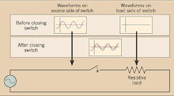
Switching a ‘normal’ load. Energizing a load begins with a switching device in the open position. When the switch is closed, the load is connected to the rest of the energized system and whatever voltage magnitude exists on the switch's source side will be applied across the load at the instant of contact touch. If the load is a pure resistance, this isn't a problem. The voltage across the resistance (shown in blue in Fig. 1 above) will give rise to a current flow (shown in red) according to Ohm's Law.
Fig. 1 also shows the switch closing just as the voltage waveform crosses zero. This is the preferred time of closing. If the switch closes at any other time, the voltage and current waveforms on the load side of the switch will experience a sudden “jump” or discontinuity. The rapidly rising voltage and current during this transient period adversely affects the system's power quality. (Part 2 of this article, which will appear in next month's issue, will explore this phenomenon in detail.)
Now let's look at how a resistive load is de-energized. Prior to de-energization, the voltage and current waveforms are in phase. At some point, the switch contacts will begin to separate. It's not physically possible to fully separate the contacts instantaneously because of the inertia associated with the contact masses that must be accelerated. One electrical cycle at 60 Hz has a period of about 16.7 msec. Most mechanical and hydraulic operators will take several electrical cycles to transition the contacts from closed to fully open. This operation, which is slow in electrical terms, will be the root cause of a serious problem.
When the switch contacts begin to open, the dielectric strength of the gap between the contacts is low, since the separation distance of the contacts is small. As the separation distance grows, so does the dielectric strength of the gap. After the voltage waveform crosses zero, its magnitude begins to grow. This voltage that builds across the separating contacts is called the recovery voltage. It may grow more quickly than the dielectric strength across the parting contacts, so current will re-establish through an arc between the contacts.
As the switch contacts continue to separate, the dielectric strength of the gap will quickly exceed the recovery voltage. When the dielectric recovery of the switching device grows more quickly than the system recovery voltage, the arc will extinguish when the current waveform next crosses zero, the current will stop flowing, and the circuit will be successfully interrupted.
Most switching devices are designed to safely dissipate the energy of the arc. A small transient disturbance will occur to the voltage waveform during the arcing, but this short-lived perturbation is usually insignificant. Fig. 2 shows the de-energizing process graphically.
Switching a capacitive load.
If the load contains inductance or capacitance, the situation is quite different. The laws of physics state that neither the current flow through an inductor nor the voltage across a capacitor can change instantaneously. In reality, some inductance and some capacitance are present in all circuits, although the values may be very small.
So, what happens when the switch is closed to energize an inductive or capacitive load? In the case of a capacitive load, the current waveform leads the voltage waveform by 90°. If the switch contacts close as the voltage waveform crosses zero, the current would have to instantaneously jump to its maximum value at that time, giving what's referred to as the “expected response” (Fig. 3). But an instantaneous change in current isn't physically possible, so instead a very fast — but not instantaneous — change in current that overshoots the maximum value takes place. The peak current inrush magnitude, as defined in the following equation, is a function of the rated capacitor current and the strength of the system to which the capacitor is connected, quantified by the available short-circuit current.
The differential equation that describes this case has a solution that contains an exponentially damped sinusoid. This transient decay occurs at a frequency much higher than the power system frequency, typically in the kilohertz range. This frequency is determined by the same parameters that defined the peak inrush current and is described by the equation below.
As the current rapidly increases, the voltage rapidly decreases, following Ohm's Law. The voltage and current waveforms oscillate, or ring, at a frequency much higher than the power system frequency. After a short period of time, the waveforms then settle down to their steady-state values, as expected. Graphically, energizing a capacitor looks like the “actual response” labeled in Fig. 3.
De-energizing a capacitive load poses even more challenges. Because the current waveform leads the voltage waveform by 90°, the current is interrupted very close to its zero crossing when the voltage is at its maximum absolute value. Looking at Fig. 4 on page 20, the initial current interruption occurs at the y-axis. At that time, both the system voltage and the voltage on the capacitor are at their maximum negative values. As the contacts open, the charge that maintains the capacitor voltage is trapped in the capacitor, thus keeping the capacitor voltage constant at its maximum negative value. The capacitor voltage is shown as a dashed black line in Fig. 4. According to IEEE Standards 18-2002 and 1036-1992, the trapped charge in a power capacitor must dissipate such that the voltage on the capacitor is no more than 50V 5 min. after de-energization. This voltage decay is very slow compared to the timeframe discussed in this article, so it's necessary to consider capacitor voltage while de-energized to be constant, as shown by the horizontal dashed black line in Fig. 4.
As the contacts in this example continue to separate — a process that will take about three electrical cycles or 50 msec at 60 Hz — the dielectric strength of the gap between them increases in a fairly linear fashion, as shown by the solid black line in Fig. 4. But the voltage difference across the contacts, which is the difference between the sinusoidal system voltage and the constant capacitor voltage, increases more quickly. At the restrike point the voltage across the parting contacts exceeds the dielectric strength of the gap between the contacts. This will cause an insulation breakdown, which will result in an arc that re-establishes current flow. This re-establishment of current flow occurs after a quarter of a cycle of initial interruption in the example. Thus, this re-establishment of current flow is called a “restrike.” Had the restrike occurred in less than a quarter of a cycle after initial interruption, it would have been called a “re-ignition.”
When the current is re-established, it becomes a high-frequency, exponentially decaying sinusoid. The high-frequency current oscillations give rise to high-frequency voltage fluctuations, similar to that of the capacitor energization case. Resistance present in the system quickly damps these oscillations.
At the next current zero, the arc will be interrupted again, but this time the contacts will be farther apart than during the first interruption attempt, thereby providing a greater dielectric strength between the parting contacts. At the second interruption attempt in the example, the dielectric strength between the parting contacts, which are still at less than half of their ultimate separation distance apart, will slightly exceed the voltage difference across the opening contacts. This will allow a successful current interruption. In some cases, a second restrike would occur at this point, and successful interruption would have to wait until the third attempt.
A capacitive switching device must be designed to endure the thermal stresses caused by the re-ignitions and restrikes. Some circuit breakers fail to meet this level of performance. This is why switching devices used for capacitor switching must be designed specifically for that application. In many cases, such devices have a higher transient recovery voltage rating than general-use circuit breakers. This makes the slope of the solid black lines labeled “dielectric strength between contacts” in Fig. 4 steeper, which reduces the probability of re-ignitions and restrikes.
Part 2 of this article will examine the detrimental effects capacitor switching has on the rest of the system and discuss the methods of minimizing them.
Fehr is an independent engineering consultant located in Clearwater, Fla.
Sidebar: Why We Use Capacitors
Capacitors have many uses in electric power systems. When used as sources of reactive power they're connected line-to-neutral, or in shunt. These shunt capacitors, which are often called “power factor correction capacitors,” are used at all voltage levels.
At the transmission and subtransmission levels (above 34.5kV), shunt capacitors increase the power transfer capability of a transmission system without requiring new lines. Due to the high cost, long lead-time, and problems associated with transmission line construction, utilities use high-voltage capacitors today more frequently than ever.
High-voltage shunt capacitors also support the transmission system voltage, which is often necessary when the transmission grid is pushed to and perhaps beyond its design limits as a result of open access to the grid and decreased capital spending on network upgrades. Since the capacitors produce reactive power (VARs), generators no longer need to produce as much, enabling them to operate at higher power factors and produce more real power (watts). Also, fewer VARs transported through the transmission system not only frees additional capacity on the lines for watts, but also reduces system losses by reducing the total current flowing on the lines.
Shunt capacitors also slightly increase transmission bus operating voltages. As the transmission voltage increases, less current is necessary to supply a typical load, so transmission losses decrease again.
Utilities use shunt capacitors at distribution and utilization voltages to provide reactive power near the inductive loads that require it. This reduces the total current flowing on the distribution feeder, which improves the voltage profile along the feeder, frees additional feeder capacity, and reduces losses. In fact, substation transformers experience lower loadings when utilities install sufficient capacitors on the distribution system. The reduced loadings not only improve contingency switching options on the distribution system, but also extend equipment life and defer expensive additions to the system.


