Meters are indispensable when working with electrical systems
Over the years, a wide variety of electrical meters has been developed to assist with monitoring and troubleshooting electrical systems. Let's take a look at some of the more common metering devices.
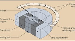
Many meters were developed using moving coil mechanisms, called D'Arsonval movements. A permanent magnet provides a uniform magnetic field into which a spring-mounted moving coil is positioned. A pointer is attached to the moving coil. The current to be measured passes through the coil, which is free to pivot. As the current passes through the coil, it produces a magnetic field that interacts with the uniform magnetic field produced by the permanent magnet. This interaction causes the moving coil and pointer to rotate. Since these movements can be precisely calibrated, they form the basis of many analog meters.
To eliminate the need for precise mechanical components and to reduce the need for calibration and adjustment, digital electronics form the basis for much metering done today. Analog voltage and current signals are converted to digital values and then displayed as numbers. Digital technology allows one metering device to display multiple values.
What can you meter?
Both analog and digital metering methods can measure many useful electrical quantities, including the following.
Voltage.
A voltmeter is put in parallel with a circuit element to measure the potential difference across that element. To minimize the current flow through the voltmeter, they're often designed with internal impedances on the order of many megohms per volt. Voltmeters can determine relay contact and switch states while the circuit is energized, easing the troubleshooting process. A zero voltage reading across the contacts indicates the contacts are closed, and a non-zero voltage indicates they're open.
Current.
Ammeters are put in series with a circuit element to measure the current flowing through that part of the circuit. To minimize the voltage drop across the meter, ammeters are designed with a very low internal impedance. Because of this low internal impedance, improperly connecting an ammeter can result in a very high current flow through the meter, which could damage the meter coil or electronics. Therefore, ammeters are typically fused to protect the meter from excessive current. Some ammeters, known as clamp-on ammeters, use a built-in current transformer, which can be clamped around a conductor to facilitate a quick and easy measurement.
Power.
Since power is essentially the product of voltage and current, you can meter power using a voltage, or potential, element and a current element. If real power is to be measured, the rms magnitudes of the voltage and current waveforms are multiplied together, and that product is multiplied by the cosine of the angle difference between the voltage and current waveforms, which is the power factor. If reactive power is to be measured, the power factor is replaced by the sine of the angle difference between the voltage and current waveforms.
Energy.
Integrating power over time yields energy; therefore, introducing a time standard to a power meter makes it possible to measure watt/hours, VAR-hours, and volt-ampere-hours. This is done electromechanically with an induction disk meter, which is essentially an induction motor that rotates at a speed proportional to the power measured by the potential and current coils. A mechanical register or odometer counts the disk revolutions. When the number of revolutions is scaled by the appropriate constants — based on the meter design — it's possible to determine the amount of energy passing through the meter.
The basic principles of metering can be used to measure other quantities like frequency, power factor, and synchronism (voltage magnitude and angle comparison) across an open circuit breaker. While some of these metering methods may be quite complex, the fundamentals of metering remain the same.


