Q. How do I size the equipment grounding conductor to a motor branch circuit?
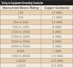
A. Equipment grounding conductors of the wire type must be sized not smaller than shown in Table 250.122, based on the rating of the circuit overcurrent device; however, the circuit equipment grounding conductor isn’t required to be larger than the circuit conductors [250.122(A)] (Table).
Section 250.122(D)(1) specifically addresses sizing the equipment grounding conductor for motor branch circuits.
Here’s an example problem to highlight how to select the proper size grounding conductor.
What size equipment grounding conductor is required for a 2-hp, 230V, single-phase motor?
Step 1: Determine the branch circuit conductor size [430.22(A) and Table 310.15(B)(16)]:
2-hp, 230V motor FLC = 12A
[Table 430.248]
12A × 1.25 = 15A
A 14 AWG conductor is rated 20A at 75°C [Table 310.15(B)(16)]
Step 2: Determine the branch circuit protection [240.6(A), 430.52(C)(1), and Table 430.248]:
12A × 2.50 = 30A
Step 3: The circuit equipment grounding conductor must be sized to the 30A overcurrent device — 10 AWG [Table 250.122], but it’s not required to be sized larger than the circuit conductors — 14 AWG [250.122(A)].
Q. What are the Code rules for sizing transformer secondary conductors?
A. A set of conductors supplying single or separate loads is permitted to be connected to a transformer secondary without overcurrent protection in accordance with 240.21(C)(1) through (6).
The permission of the “next-size-up” protection rule when the conductor ampacity doesn’t correspond with the standard size overcurrent protection device of Sec. 240.4(B) doesn’t apply to transformer secondary conductors.
The primary overcurrent device sized in accordance with Sec. 450.3(B) is considered suitable to protect the secondary conductors of a 2-wire (single-voltage) system, provided the primary overcurrent device doesn’t exceed the value determined by multiplying the secondary conductor ampacity by the secondary-to-primary transformer voltage ratio.
Let’s run through an example problem to make sure you understand these requirements.
What’s the minimum size secondary conductor required for a 2-wire, 480V to 120V transformer rated 1.50kVA with 60°C terminals?
Primary Current = VA ÷ E = 1,500VA ÷ 480V = 3.13A
Primary Protection [450.3(B)] = 3.13A × 1.67 = 5.22A (or 5A fuse)
Secondary Current = 1,500VA ÷ 120V = 12.50A
Secondary Conductor = 12 AWG, rated 20A at 60°C [Table 310.15(B)(16)]
The 5A primary overcurrent device can be used to protect 12 AWG secondary conductors because it doesn’t exceed the value determined by multiplying the secondary conductor ampacity by the secondary-to-primary transformer voltage ratio.
20A secondary conductor ampacity × 120V ÷ 480V = 5A, which is equal to or less than the primary protection
Secondary conductors can be run up to 10 ft without overcurrent protection if installed as follows:
1) The ampacity of the secondary conductor must not be less than:
a. The calculated load in accordance with Art. 220, and
b. The rating of the overcurrent device at the termination of the secondary conductors
Exception: Listed equipment, such as a surge protection device, can have their conductors sized in accordance with the manufacturer’s instructions.
2) The secondary conductors must not extend beyond the switchboard, switchgear, panelboard, disconnecting means, or control devices they supply.
3) The secondary conductors are enclosed in a raceway.
4) Not less than 10% of the rating of the overcurrent device protecting the primary of the transformer, multiplied by the primary-to-secondary transformer voltage ratio.
Outside secondary conductors can be of unlimited length, without overcurrent protection at the point they receive their supply, if they’re installed as follows:
1) The conductors are suitably protected from physical damage in a raceway or manner approved by the authority having jurisdiction.
2) The conductors must terminate at a single circuit breaker or a single set of fuses that limit the load to the ampacity of the conductors.
3) The overcurrent device for the ungrounded conductors is an integral part of a disconnecting means or it’s located immediately adjacent thereto.
4) The disconnecting means is located at a readily accessible location that complies with one of the following:
a. Outside of a building.
b. Inside, nearest the point of entrance of the conductors.
c. If installed in accordance with 230.6, nearest the point of entrance of the conductors.
Secondary conductors from a feeder tapped transformer must be installed in accordance with Sec. 240.21(B)(3).
Secondary conductors can be run up to 25 ft without overcurrent protection if they comply with all of the following:
1) The secondary conductors have an ampacity not less than the value of the primary-to-secondary voltage ratio multiplied by one-third of the rating of the overcurrent device that protects the primary of the transformer.
2) Secondary conductors terminate in a single circuit breaker or set of fuses rated no more than the tap conductor ampacity in accordance with 310.15 [Table 310.15(B)(16)].
3) The secondary conductors are protected from physical damage by being enclosed in a manner approved by the authority having jurisdiction, such as within a raceway.
Service conductors — service conductors must be protected against overload in accordance with Sec. 230.90 and Sec. 230.91.
Battery conductors — overcurrent protection is installed as close as practicable to the storage battery terminals.


