The Hows and Whys of IG Wiring
It's hard to buy a new electrical device these days that doesn't contain electronics. Adjustable-speed and variable-frequency drives are now almost always connected to AC motors. Electronic ballasts are being coupled to gas discharge lighting products. Even circuit breakers and relays are mostly electronics-based in design. But with the expanded use of electronic equipment comes greater sensitivity to power disturbances and electromagnetic interference (EMI), along with its resulting operational problems.
Because equipment ground potentials (or changes in them) can affect the operation of certain electronic devices, designers, installers, and service personnel often have very specific and sometimes special grounding requirements. Most of these techniques have evolved based on empirical (trial-and-error) testing rather than on detailed analysis. Some of the more creative grounding arrangements are devised in the name of electrical noise reduction (see What's Electrical Noise?), but they often ignore the basic principles of electricity, such as electricity follows the paths of least impedance, flows in complete paths, and flows because there is a potential difference. Furthermore, when trying to reduce the effects of “noise,” the fundamentals of noise coupling are sometimes ignored.
One such special grounding technique used in low-voltage AC power systems to reduce interference is known as an isolated ground (IG). IG is allowed by the National Electrical Code and is an exception to the standard grounding requirements. Section 250.96(B) allows IG wiring only “where installed for the reduction of electrical noise (electromagnetic interference) on the grounding circuit.”
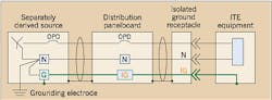
Figure 1 is an example of a typical low-voltage power system using IG receptacles, as allowed by the NEC. Note that the ground terminal of the receptacle is not connected to the conduit grounding system at the receptacle. Instead, an IG wire is connected to the receptacle ground terminal and is routed with the power conductors, passing through one or more panelboards, remaining insulated from the metal conduit and enclosure grounding system until its termination at the power system grounding point (at the service entrance or separately derived source, as shown in this example).
IG wiring and ground-fault current
It's just as important that the IG wiring provide an effective ground-fault path from the connected equipment back to the power source. If a ground fault were to occur at the load equipment, the IG grounding system would provide an effective ground path, as shown in Fig. 2. The IG conductor is permanent and continuous, has ample current capacity — because it's sized according to NEC requirements — and has a low enough impedance path to allow the overcurrent protective device (OPD) to clear the ground fault.
One other form of IG wiring for hardwired load equipment is allowed by the NEC in Sec. 250-96(B), where “an equipment enclosure supplied by a branch circuit shall be permitted to be isolated from a raceway containing circuits supplying only that equipment by one or more listed nonmetallic raceway fittings located at the point of attachment of the raceway to the equipment enclosure” (Fig. 3). In this way, the equipment ground is isolated from the metal conduit and raceway system at the load equipment but is still effectively grounded for safety — the same as previously discussed for IG receptacles.
Unsafe and incorrect IG wiring
Sometimes, IG requirements are misinterpreted, and IG circuits are thought to be truly isolated. Efforts are wrongly made to ensure that the sensitive equipment-grounding conductor is connected to an isolated dedicated ground and is never to be connected to the “dirty” power ground. Figure 4 is an example of just such an incorrect interpretation of an IG. Here, the ground terminals of IG receptacles are collected at an IG busbar and are then connected to a separate earth grounding electrode.
Sometimes, extraordinary attempts are made to ensure a good connection to the earth for the dedicated grounding electrode in the hopes of providing a “quiet ground” for some sensitive electronic system. Despite the good intentions of the isolated IG approach shown in Figure 4, it fails to meet the basic safety requirements of the grounding system. This “isolated IG” approach does not provide the effective ground path required by the NEC and results in an unsafe and hazardous condition.
Consider the possibility of a ground fault occurring at the load equipment, as depicted in Fig. 5. Note that an effective ground path is not provided between the isolated, dedicated ground and the power source grounding electrode system. It is not known if the ground path between these two earth electrodes is permanent and continuous or of ample current-carrying capacity. Furthermore, the ground path surely does not have a low enough impedance to allow the OPD to clear the ground fault quickly and safely. The impedance of ground electrode connections to earth is measured in ohms, while the required ground-fault path impedance must be in the milliohms.
Additionally, any difference in potential occurring between the isolated dedicated ground electrode and the power system grounding electrode (which must exist because one is referred to as the “quiet” ground and the other as the “dirty” ground) will appear as a common-mode (N-G) voltage at the load equipment. Although the original intent of this isolated IG approach is to reduce electrical noise, the result is actually an increase in the common-mode noise potentials at the sensitive loads.
Significant ground potential differences can occur whenever there are large ground currents flowing, such as during ground faults, lightning, or even when electrical storm clouds (charged) move over the area. A common result of incorrect isolated IG wiring during these events is damage to the connected load equipment.
One interesting observation of incorrect and unsafe grounding practices is that the equipment may still operate even though it's improperly grounded — and the safety hazard may occur only under a specific set of conditions, such as during a ground fault or a lightning storm.
Perhaps the term “isolated ground” contributes to the misinterpretation of the IG wiring techniques. A better term would be “insulated ground,” because the intent of IG is not to isolate the ground of the sensitive load from the power system ground, but rather to insulate it and to control where the connection to the power system ground is made.
Benefits of IG wiring techniques
The late Warren Lewis, a true pioneer in power quality and grounding technologies, once stated, “IG wiring, when properly implemented, is an important power quality enhancement tool that sometimes improves the noise situation, sometimes has no effect, and at other times makes the condition worse. The trick is obviously in knowing which time is which!”
Often, electronics engineers will balk at the proper implementation of IG wiring, as shown in Fig. 5, because they see no isolation of the sensitive electronic equipment ground path. A typical comment is, “What good is it when the IG is connected to the ‘dirty’ AC power ground, as required for safety?” The obvious answer is that the conduit and metal enclosure system provide EMI/RFI shielding of the power and IG conductors contained within them. But that's only part of the benefit of IG wiring.
A more practical benefit is that IG wiring controls the grounding connections of the sensitive electronic equipment to minimize the problems associated with stray ground currents. Consider the example shown in Fig. 6 for a standard (non-IG) grounding configuration. Stray ground currents flowing on the grounding system cause changes in the ground potentials throughout the grounding system. These currents are a reality with virtually every power system and exist under a variety of conditions, most of which are very dynamic (as opposed to steady-state). Stray ground currents can be the result of electrostatic discharge to the enclosures, ground-fault currents, or even the capacitively coupled ground current surge when a load is energized.
For the example shown in Fig. 6, any stray ground current will cause the ground potential of the panelboard enclosure to rise relative to the power ground reference at the neutral-to-ground bonding point. With the standard grounding configuration, the computer system's equipment ground reference relative to the power ground will also rise because the ground terminal at the panelboard is connected to the enclosure and changes as the enclosure's ground potential changes.
An alternative IG configuration is shown in Fig. 7, where the equipment ground reference for the sensitive load is isolated from the metal conduit and enclosure ground system. Stray ground currents flowing on the conduit and enclosure system cause ground potential changes that are confined to the conduit and enclosure grounding system. Because the stray ground currents do not flow on the IG wiring, they do not affect (upset) the sensitive electronic equipment's ground reference.
Disadvantages of IG wiring techniques
Now that we've stated the potential benefits of IG wiring techniques, it's time to look at potential disadvantages, one of which involves induced currents from the power conductors.
Consider the relative position of the ground (or IG) conductor to the power conductors in a raceway. Figure 8 shows the cross-section of two possible configurations. In most building electrical raceways, the position of the ground conductor is, at best, random relative to the power conductors, because multiple individual conductors are normally used (instead of a manufactured cable where the relative position of the conductors is controlled).
Whenever the ground conductor is not equally spaced between the power conductors, the magnetic fields associated with the currents flowing in the power conductors will not be balanced in the ground conductor. This net magnetic field, being an AC magnetic field, will induce current into the ground conductor if the ground conductor is part of a complete path for the current to flow (ground loop).
IG circuits might be considered a solution to the induced ground current problem, because the IG conductor is terminated to ground at only one end and does not form a complete loop through which the current can flow. This would be true as long as the load equipment served by the IG receptacle does not have any other connections to the power system ground. For interconnected systems, those having more than one piece of load equipment connected together by way of data, communication, or control cables, the use of IG wiring can actually make the induced current problem worse.
Consider the interconnected system shown in Fig. 9. The interconnecting data, communication, or control cable completes a loop for the induced current in the IG conductor. Currents induced by the power conductors are forced to flow on the interconnecting cables, where there is a greater chance of upsetting or damaging the sensitive load.
Induced currents on the interconnecting cabling of interconnected systems has led to the widespread practice of grounding the shield of the interconnecting cable at only one end. While this practice may break up the potentially disruptive ground loop, it allows for the possibility of damaging or unsafe voltages to be developed in the system, particularly during ground fault, lightning, or other surge events.
Induced currents on the interconnecting cables can be particularly troublesome for sensitive electronic systems having signals on the interconnecting cables, which can be upset by the power system frequencies (60 Hz and the harmonics of 60 Hz). Examples of systems that have been observed to be sensitive to the power system frequencies include audio and video equipment and analog signal processors.
Standard grounding techniques, which use an insulated equipment-grounding conductor connected to all of the metal enclosures, are less prone to problems with induced ground currents caused by the power conductors (Fig. 10). Whenever an insulated ground conductor is routed with individual power conductors, the resulting net magnetic fields from the power conductors will induce currents into any loop involving the insulated ground conductor.
With standard grounding techniques, the metal conduit or raceway is electrically in parallel with the insulated ground conductor. The resulting induced ground current will flow without practical consequence in the ground conductor and conduit system. The induced current is diverted away from and normally will not flow in the typically higher impedance loop involving the interconnecting data, communication, or control cables.
Sometimes, IG wiring techniques are inadvertently implemented. Such is the case when nonmetallic conduit or enclosures are used — not because they interrupt the metal conduit system, but for environmental reasons, such as in corrosive environments or because of direct burial in the earth or concrete. Because the raceway does not provide an effective ground path, an insulated ground conductor is used. This nonmetallic raceway system shares some of the characteristics of IG wiring, since the insulated ground conductors typically have only one connection to the power system ground.
The nonmetallic raceway system also has the same concerns with induced ground currents and interconnected systems as IG wiring. One significant difference of the nonmetallic raceway system from the IG wiring techniques discussed previously is that nonmetallic raceway systems do not provide the EMI/RFI shielding of metallic raceway systems.
In Summary
Whether IG wiring is beneficial or not depends on particular noise coupling modes, the sensitive equipment's susceptibility to ground potential shifts or induced ground currents, and the power system configuration.
IG wiring is not isolated from the power system grounding. For safety reasons, the IG wire must be connected to the power system ground to ensure effective grounding of the load equipment. A better term for IG would be “insulated ground,” because the intent of IG wiring is to insulate the grounding of the sensitive load equipment from the conduit grounding system and to control the connection to the power grounding system.
IG techniques can be useful to reduce the common-mode noise appearing at the sensitive load equipment by providing EMI/RFI shielding and by eliminating the ground potential shifts due to stray ground currents flowing in the conduit system. However, with interconnected sensitive equipment, IG wiring can have a detrimental effect due to the induced currents flowing on the interconnecting cabling.
Gruzs is an account representative with Emerson Network Power in Columbus, Ohio. He can be reached at [email protected].
Sidebar: What's Electrical Noise?
Common-mode noise is any unwanted signal that is common to all circuit conductors simultaneously. The other form of noise is normal-mode noise (also known as transverse or differential-mode noise), which is any unwanted signal that exists between the circuit conductors.
In AC power systems, the difference in potential between neutral and ground is one form of common-mode noise, because any change in neutral potential relative to ground also affects all of the other power circuit conductor potentials to ground. Another more troublesome form of common-mode noise is the differences in ground potentials throughout an electrical system.
When multiple electronic devices are interconnected by way of control, data, or communication cables, any difference in ground potentials between the interconnected pieces of equipment is common-mode noise to the control, data, or communication circuits. It's virtually impossible to keep all of the (chassis) ground potentials of distributed electronic devices at the same potential under all possible circumstances. Therefore, manufacturers design some level of common-mode noise immunity into electronic devices that are intended to be interconnected. Furthermore, the surge suppression, wiring, shielding, and grounding of the building electrical system (including the control, data, and communication cabling) can have a pronounced effect on the levels of common-mode signals to which the electronics are exposed.